background image

Preface

9

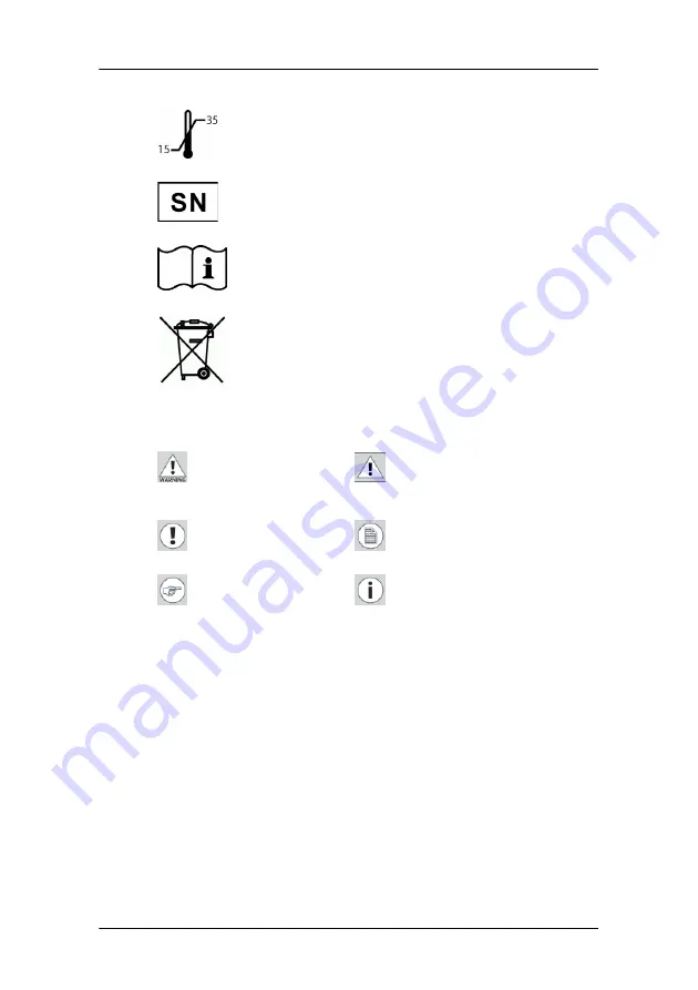
Symbols used throughout the manual:

Indicates the temperature limitations for the 
display to operate within specs

Indicates the display serial no.

Consult the operating instructions

Indicates this apparatus must not be thrown 
in the trash but must be recycled, according 
to the European WEEE (Waste Electrical and 
Electronic Equipment) directive

Warning: Risk of 
injury to human 
beings

Caution: Risk of 
damage to the 
product

Important notice or 
remark

Note

Hint, tip

Additional 
information

Summary of Contents for MIVD 1218 MKII

Page 1: ...Installation User Manual MIVD 1218 MKII...

Page 2: ...This page intentionally left blank 2 This page intentionally left blank...

Page 3: ...stand 17 Operation 19 Stand by switching 19 About the On Screen Display OSD 20 Adjustments for a digital video signal 25 Adjustments for an analog video signal 25 Standard OSD functions 27 Advanced O...

Page 4: ...se let us know BarcoView software products are the property of BarcoView They are distributed under copyright by Barco N V or BarcoView LLC for use only under the specific terms of a software license...

Page 5: ...ian notice This ISM device complies with Canadian ICES 001 Cet appareil ISM est conforme la norme NMB 001 du Canada Disposal Information The lamps inside the display contain mercury Do not throw the d...

Page 6: ...for 240V application Do not overload wall outlets and extension cords as this may result in fire or electric shock Mains lead protection U S Power cord Power cords should be routed so that they are no...

Page 7: ...age may result in some image sticking on the LCD panel Over 10 hours operation with the same image content is not recommended Switching on DPMS on display and PC and activating a good screen saver may...

Page 8: ...2 EEC or Indicates the display is approved according to the UL regulations or Indicates the display is approved according to the c UL regulations Indicates the display is approved according to the DEM...

Page 9: ...erial no Consult the operating instructions Indicates this apparatus must not be thrown in the trash but must be recycled according to the European WEEE Waste Electrical and Electronic Equipment direc...

Page 10: ...the overall optical efficiency and provides long term image confidence Ambient Light Compensation ALC When enabled the ALC system automatically adapts the display light output depending on the ambient...

Page 11: ...ivel foot allows ideal positioning of the panel in height and viewing angle Most of the illustrations in this manual show the model with the tilt swivel foot option Parts controls and connectors Front...

Page 12: ...trol wheel The control wheel can be pressed like a push button and rotated like a knob It allows to put the display in stand by navigate through the on screen display OSD menus and change values in th...

Page 13: ...monochrome video input Video amplitude 500 950 mV Sync amplitude for composite video 200 400 mV 4 Composite or Horizontal Sync CS HS input Amplitude 500 mV to 5V 5 Vertical Sync VS input Amplitude 500...

Page 14: ...or desk desktop version Keep the display away from heat sources and provide enough ventilation around the display Display installation Power connection To connect the power 1 To get access to the conn...

Page 15: ...han 1 input is connected you can switch inputs by using the display s on screen display Connecting DVI analog or digital signals 1 Connect one end of the DVI cable to the DVI input of the display Figu...

Page 16: ...chrome You should use a proper video cable e g from VGA to BNC This cable is not delivered with the display Proceed as follows 1 Connect one end of the signal cable to the analog video output monochro...

Page 17: ...e inside the connector compartment Put the connector compartment cover back on the display Pay attention that the signal cables are positioned under the bulge in the cover Attaching the display to an...

Page 18: ...Installation 18 To attach the display to an arm stand 1 Attach the arm stand firmly to the panel using 4 screws M4 x 8 mm Figure 8 4 screws M4 x 8mm...

Page 19: ...hing on DPMS on display and PC and activating a good screen saver may decrease the risk of image sticking image retention Stand by switching When the display is on and no on screen display is visible...

Page 20: ...e the chapter about the Advanced OSD functions you can determine which menus will appear in the Quick OSD When the on screen display OSD is not on the screen press the control wheel shortly to display...

Page 21: ...apter about the Extended OSD functions About the Extended OSD The Extended OSD has a hierarchical tree structure with several levels The top level is the Main Menu The items from the main menu contain...

Page 22: ...e the digital video signal requires less adjustment than the analog video signal It is indicated throughout this manual if a function is not present when DVI input is selected Main menu and submenu MI...

Page 23: ...not on the screen rotate the control wheel to display the Extended OSD The main menu appears 2 To enter into a menu First rotate the control wheel to select the desired menu Next press the wheel shor...

Page 24: ...The adjustment name appears as well as the current adjustment value Rotate the wheel to change the value When done press the wheel shortly to confirm the change and return to the menu 5 To select a va...

Page 25: ...tments are necessary when a digital video signal is connected and selected However if necessary you can perform manual adjustments Please refer to the description of the OSD functions further in this...

Page 26: ...deo amplitude E g a Windows desktop pattern would be a good image provided the background is not too dark The image should contain sharp black white transitions like a line pattern or characters The i...

Page 27: ...luminance to which the display will be stabilized Yes Adjustments Perform Geometry and Phase adjust ments Yes Input Selection Select which video signal will be dis played DVI D DVI A BNC or VGA Yes S...

Page 28: ...n intensity of at least 15 video amplitude Name Description Full Autoset Perform all Autoset functions below one after another Automatic Gain Adjust the video levels black and white automatically Auto...

Page 29: ...image Therefore we advise to leave video contrast in calibrated position Video Brightness This menu is not available in DVI mode Video brightness adjusts all levels in the image on the screen from dar...

Page 30: ...of the image on the screen When Ambient Light Compensation ALC is switched on the manual luminance adjustment will not work Instead the OSD shows ALC Active ALC can be switched on off in the Settings...

Page 31: ...djust to resize the image and the active video window horizontally A value of 100 means the image is not resized Yes Hor Pos Position the image horizontally inside the active video window No Vert Pos...

Page 32: ...Adjust the video sampling frequency manually This is necessary when you notice abnor mal vertical banding which can be seen best on a dot on dot off pattern The figure in the OSD is the total number...

Page 33: ...off the automatic power saving system DPMS Power LED Switch the power LED on off Note The LED s orange DPMS state is not influenced by this setting So when the display goes into power saving mode the...

Page 34: ...rmation about the Presets please consult the Glossary section Name Description Find next preset Select another Preset from memory that matches the incoming video and sync sig nals The number displayed...

Page 35: ...icates the total time the display has been operating including the time in stand by Backlight Lifetime Indicates the total time the display has been operating excluding the time in stand by Name Descr...

Page 36: ...unctions The advanced functions are extensions of the standard OSD By default a user browsing through the OSD sees only the standard functions When logged in in advanced mode the user sees the standar...

Page 37: ...two functions to set the mini mum point of the ALC control system Min Ambient Light Enter the value in Lux of the darkest possible ambient light condition you are likely to work in Min Luminance Ente...

Page 38: ...hapter about locking and unlocking user controls to know how to use this function Input Mode To change the Input Mode setting press the control wheel Rotate the wheel to select Standard or Extended in...

Page 39: ...Quick OSD If all possible menus are excluded the Quick OSD will not appear on the screen Name Description RGB RGB The R video signal drives the R sub pix els the G video signal drives the G sub pixel...

Page 40: ...ight Runtime indicates the time the backlight has been on since the last time it was switched off e g in stand by This counter stops after 1092 minutes Service Service information is a submenu from Ge...

Page 41: ...s 2 Rotate the control wheel to select Exit 3 Press and hold the control wheel until the Advanced Main Menu appears This is indicated by an asterisk in the menu header 4 Rotate the control wheel to se...

Page 42: ...at the display is completely off This is not the Stand By mode The power LED must be off 2 Press and hold the control wheel Then power up the display again Release the control wheel after 2 seconds 3...

Page 43: ...ng cloth DO NOT USE Lye or cleaning solutions containing lye Acid Detergents with fluoride Detergents with ammonia Detergents with abrasives Steel wool Sponge with abrasives Cloth with thread made of...

Page 44: ...lightly moistened with a recognized cleaning product for medical equipment Repeat with water only Wipe dry with a dry cloth The cabinet has been tested for resistance to the following products Cidex B...

Page 45: ...by Check in the Windows Display Properties if the display controller video heads are attached If not there will be no image on the screen The external power supply may be defective Image exhibits noi...

Page 46: ...has been on the screen for a long time The ghost image will disappear after some time Over 10 hours operation with the same image content is not recommended Switching on the display DPMS may decrease...

Page 47: ...ical 170 Horizontal 170 Pixel Pitch 0 2805 mm H x 0 2805 mm V Native color resolution 8 bits sub pixel Luminance 400 cd m calibrated Contrast ratio 550 1 on off in dark environment Response time 20 ms...

Page 48: ...mensions W x H x D 432 x 362 2 x 107 mm Net weight 9 1 kg Operating Temperature 0 C to 40 C 15 C to 35 C within specs Storage Temperature 20 C to 60 C Humidity 8 80 non condensing for operation 5 95 n...

Page 49: ...DATA 2 16 HOT PLUG DETECT 2 TMDS DATA 2 17 TMDS DATA 0 3 GND 18 TMDS DATA 0 4 NC 19 GND 5 NC 20 NC 6 DDC CLOCK 21 NC 7 DDC DATA 22 GND 8 Analog VS 23 TMDS CLOCK 9 TMDS DATA 1 24 TMDS CLOCK 10 TMDS DAT...

Page 50: ...r After this calibration black and white luminance are set to the ideal level A stabilization routine constantly active when the display is on keeps these levels constant using the built in sensor Pin...

Page 51: ...Association NEMA The standard specifies how digital image data can be moved from system to system In addition Supplement 28 Part 14 specifies a function that relates pixel values to displayed Luminanc...

Page 52: ...ustomer and shall advise the Customer on how to proceed Customer Support may ask to return the faulty equipment or faulty subassemblies to the BarcoView Customer Support Center or an authorized servic...

Page 53: ...2 5 Any failures resulting from an accident negligence such as but not limited to removing or deleting system files licensed software product files misuse circuit failure or any change damage due to...

Page 54: ...implied warranties of merchantability and fitness for a particular purpose ARTICLE 6 LIMITATION OF LIABILITY Barcoview shall not under any circumstances be liable to customer or any third party for di...

Page 55: ...hinder performance by one party of his obligations ARTICLE 8 GENERAL 8 1 Customer acknowledges its understanding that all software and electronic devices including BarcoView products are subject to p...

Page 56: ...www barco com K5904081 01 October 2006...

Reviews: