background image

63

R5913964 /00

MDSC-8255

Symbols on the box

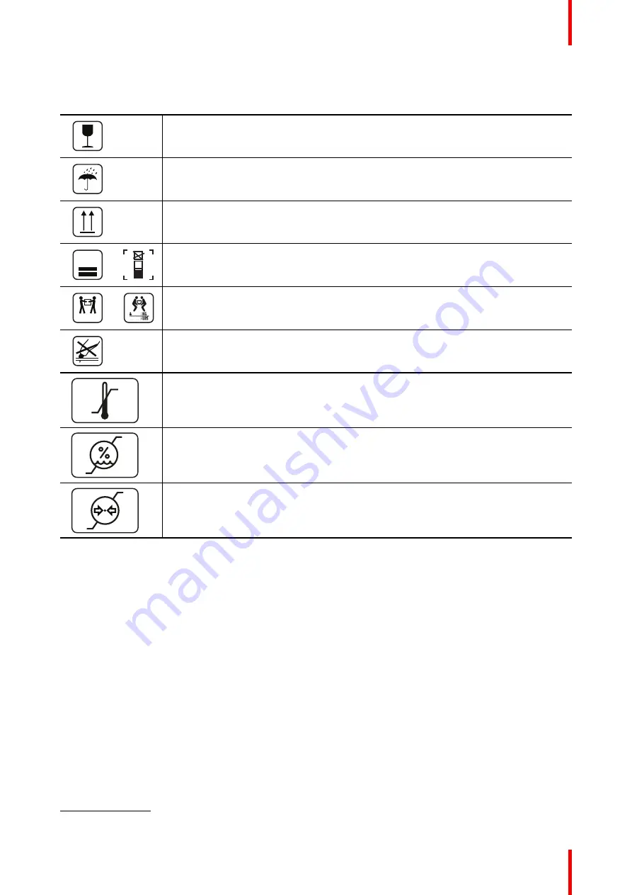
On the box of the device, you may find the following symbols (nonrestrictive list):

Indicates a device that can be broken or damaged if not handled carefully when being
stored.

Indicates a device that needs to be protected from moisture when being stored.

Indicates the storage direction of the box. The box must be transported, handled and
stored in such a way that the arrows always point upwards.

15

n

or

n

Indicates the maximum number of identical boxes which may be stacked on each
other, where

n

is the limiting number.

xx-yy Kg

or

xx-yy

xx-yy

Indicates the weight of the box and that it should be carried with two persons.

Indicates that the box should not be cut with a knife, a cutter or any other sharp object.

-20 °C

+60 °C

xx

yy

Indicates the temperature limits

6

to which the device can be safely exposed when

being stored.

85 %

5 %

x

yy

Indicates the range

6

of humidity to which the device can be safely exposed when being

stored.

106 kPa

50 kPa

xx

yyy

Indicates the range

6

of atmospheric pressure to which the device can be safely

exposed when being stored.

6.8 Legal disclaimer

Disclaimer notice

Although every attempt has been made to achieve technical accuracy in this document, we assume no
responsibility for errors that may be found. Our goal is to provide you with the most accurate and usable
documentation possible; if you discover errors, please let us know.

Barco software products are the property of Barco. They are distributed under copyright by Barco NV or Barco
Inc., for use only under the specific terms of a software license agreement between Barco NV or Barco Inc.
and the licensee. No other use, duplication, or disclosure of a Barco software product, in any form, is
authorized.

The specifications of Barco products are subject to change without notice.

Trademarks

All trademarks and registered trademarks are property of their respective owners.

Important information

6.

Values for xx and yy can be found in the technical specifications paragraph.

Summary of Contents for MDSC-8255 12G

Page 1: ...ENABLING BRIGHT OUTCOMES MDSC 8255 LED MDSC 8255 MNA MDSC 8255 12G User Guide 55 UHD 4K surgical display MDSC 8255 ...

Page 2: ...Registered office Barco NV President Kennedypark 35 8500 Kortrijk Belgium www barco com en support www barco com Barco NV Beneluxpark 21 8500 Kortrijk Belgium www barco com en support www barco com ...

Page 3: ... 2 4 2 USB type A connector 15 2 4 3 USB type B connector 15 2 4 4 Micro USB connector 15 2 4 5 DisplayPort connector 16 2 4 6 HDMI connector 16 2 4 7 DC out connector 17 3 Installation 19 3 1 Interface connection 20 3 1 1 MDSC 8255 LED 20 3 1 2 MDSC 8255 MNA 21 3 1 3 MDSC 8255 12G 22 3 2 Power connection 23 3 3 VESA mount installation 24 4 Daily operation 27 4 1 On Off switching 28 4 2 Power mode...

Page 4: ...2G 40 5 3 5 Auto search 40 5 3 6 Failover input MDSC 8255 LED MNA 40 5 3 7 Failover input MDSC 8255 12G 41 5 3 8 Picture and Picture input MDSC 8255 LED MNA 42 5 3 9 Picture and Picture input MDSC 8255 12G 43 5 3 10 Picture in Picture input MDSC 8255 LED MNA 43 5 3 11 Picture in Picture input MDSC 8255 12G 44 5 3 12 Picture in Picture mode 44 5 3 13 Picture in Picture position 45 5 3 14 Picture in...

Page 5: ... 00 MDSC 8255 6 4 Cleaning instructions 55 6 5 Regulatory compliance information 56 6 6 EMC notice 57 6 7 Explanation of symbols 60 6 8 Legal disclaimer 63 6 9 Technical specifications 64 6 10 Troubleshooting 69 ...

Page 6: ...R5913964 00 MDSC 8255 6 ...

Page 7: ...7 R5913964 00 MDSC 8255 Welcome 1 ...

Page 8: ...020 High color depth with 10 bit per color Backlight Output Stabilization over time Advanced full 10 bit image processing algorithms with 14 bit LUT UHD 3840x2160 FHD and legacy input accepted Innovative features are available to give maximum flexibility when installing the display The Failover Mode for example ensures a backup signal is always available for safe surgery 1 2 What s in the box Over...

Page 9: ... may be used in this user guide In descending order of importance they are WARNING Describes hazards or dangers that might result in personal injury or death CAUTION Describes hazards that could damage the product Gives additional information about the described subject Gives extra advice about the described subject Welcome ...

Page 10: ...R5913964 00 MDSC 8255 10 Welcome ...

Page 11: ...11 R5913964 00 MDSC 8255 Parts controls and connectors 2 ...

Page 12: ...display 1 Input selection key 2 Down key 3 Up key 4 OSD menu key Enter key 5 Brightness decrease Left key 6 Brightness increase Right key 7 Standby key 8 Power mode LED 2 2 Rear view Overview 1 2 Image 2 2 1 VESA mount screw holes VESA 200 mm and up 2 Protective earth pin for additional grounding Parts controls and connectors ...

Page 13: ...z power in The BNC SDI connectors match the characteristic impedance of 75 ohm cables 2 3 2 MDSC 8255 MNA Overview 11 5 13 17 14 15 16 10 9 6 8 7 5 4 3 2 1 Main 1 2nd 2 18 12 Image 2 4 1 Headphone out 2 Microphone in 3 Audio line out 4 Audio line in 5 USB 2 0 type A interface 4 x 6 USB 2 0 micro B interface for service use only 7 2 Secondary SFP 10Gb optical Ethernet interface 8 1 Main SFP 10Gb op...

Page 14: ...bottom right 4 SDI 4 Single link out or Quad link in bottom left 5 HDMI 2 in 6 HDMI 1 in 7 5 VDC 2 A power out connector type mating connector HIROSE RP34L 5PA 2SC 8 USB 2 0 type A interface 9 USB 2 0 type B interface 10 Main Right DisplayPort in 11 DVI D in 12 DVI D out 13 Potential Equalization pin POAG 14 2nd Left DisplayPort in 15 100 240 VAC 50 60 Hz power in See SDI config only for MDSC 8255...

Page 15: ...8 D0_Rx T M D S 19 GND data 0 shield 20 Not connected 21 Not connected 22 GND clock shield 23 CK_Rx T M D S 24 CK_Rx T M D S 5 VDC output selectable on either pin 14 or 16 via the OSD menu 5V 10 500mA max 2 4 2 USB type A connector Overview Image 2 7 1 5 VDC 2 Data 3 Data 4 GND 2 4 3 USB type B connector Overview 1 2 3 4 Image 2 8 1 Data 2 5 VDC 3 Data 4 GND 2 4 4 Micro USB connector Overview 1 2 ...

Page 16: ... 12 ML_Lane 0 p 13 CONFIG1 14 CONFIG2 15 AUX CH p 16 GND 17 AUX CH n 18 Hot Plug 19 Return 20 DP_PWR 3 3 VDC 500 mA max 2 4 6 HDMI connector Overview 1 2 4 6 8 10 12 14 16 18 3 5 7 9 11 13 15 17 19 Image 2 11 1 T M D S Data2 2 T M D S Data2 Shield 3 T M D S Data2 4 T M D S Data1 5 T M D S Data1 Shield 6 T M D S Data1 7 T M D S Data0 8 T M D S Data0 Shield 9 T M D S Data0 10 T M D S Clock 11 T M D ...

Page 17: ...3964 00 MDSC 8255 16 DDC_SDA 17 DDC CEC GND 18 5VDC POWER 19 HDP 2 4 7 DC out connector Overview 1 2 Image 2 12 1 5 VDC 2 GND Connector type mating connector HIROSE RP34L 5PA 2SC Parts controls and connectors ...

Page 18: ...R5913964 00 MDSC 8255 18 Parts controls and connectors ...

Page 19: ...19 R5913964 00 MDSC 8255 Installation 3 ...

Page 20: ...ween surgical suites To connect your MDSC 8255 to Barco s Nexxis OR system connect the 10Gb Ethernet interface to your Nexxis switch More info about Nexxis OR and how to configure the MDSC 8255 in your network is available in the dedicated user guides Please visit www barco com to obtain these user guides Nexxis OR is only available on the MDSC 8255 MNA version 3 1 1 MDSC 8255 LED To connect the i...

Page 21: ...ations page 64 2 When the SDI video input is connected an additional SDI video sink can be connected to the SDI output SDI input loop through 3 Screen image clone The entire active image on the screen including OSD can be duplicated to a FHD 1080p 1080i signal on the DVI output connector to which an additional DVI video sink can be connected 4 Use any USB peripheral keyboard mouse webcam by connec...

Page 22: ... 1 Connect one or more video source s to the corresponding video inputs of the display For a list of supported video inputs see Technical specifications page 64 See SDI config only for MDSC 8255 12G page 40 about the possible SDI configuration modes 2 Screen image clone The entire active image on the screen including OSD can be duplicated to a FHD 1080p 1080i signal on the DVI output connector to ...

Page 23: ...55R cables with a length of up to 30 m are recommended The DVI output must be enabled in the OSD menu please refer to DVI output page 48 A subset of the commands of the remote control protocol is also available on a new DDC protocol on DVI and DisplayPort1 auxiliary channel 3 2 Power connection To connect the power Connect the power input of your display with a grounded power outlet by means of th...

Page 24: ...irements regarding maximum admitted cable length Use the included M4 screw to attach the wire to the protective earth pin Image 3 6 3 3 VESA mount installation To install the display on a VESA mounting solution The display can be attached to a VESA 200 mm or VESA 600 mm arm or stand Image 3 7 The VESA mounting holes at the back of the display are provided with M6 type blind fasteners to fix the VE...

Page 25: ... when fixing the VESA mounting plate CAUTION Use an arm that is in compliance with VESA requirements CAUTION The monitor VESA interface has been designed for a safety factor 6 to support 6 times the monitor weight In the medical system use an arm with suitable safety factor IEC60601 1 Installation ...

Page 26: ...R5913964 00 MDSC 8255 26 Installation ...

Page 27: ...27 R5913964 00 MDSC 8255 Daily operation 4 ...

Page 28: ... for signal Note When Power save mode is enabled the display will automatically go into power save mode after 10 seconds of searching without signal Full green Display has a valid input signal 4 3 OSD menu activation To activate the OSD menu Press the key on the display As a result the OSD main menu comes up in the bottom right corner of the screen If no further actions are taken within the follow...

Page 29: ...o select the top menu item that will be highlighted Use the or keys to move to other Menu Items then press the key to select it If the selected menu item is controlled by a slider use the or keys to adjust the item value then press the key to confirm If the selected menu item is a multiple choices menu use the or keys to select the desired option then press the key to confirm Press again or key to...

Page 30: ...Control lock page 47 4 5 2 Brightness adjustment To quickly adjust the brightness While no OSD menu is on the screen press the or key to adjust the brightness as desired Brightness 50 Image 4 4 4 6 Control lock OSD menu locking unlocking About the control lock As described in Control lock page 47 the control lock can be enabled to avoid unwanted access When the OSD is locked pressing the key after...

Page 31: ... Each time a key is pressed an asterisk is shown in the square boxes After pressing the fourth key if the sequence is correct the OSD main menu is activated After exit the OSD menu will automatically lock again Daily operation ...

Page 32: ...R5913964 00 MDSC 8255 32 Daily operation ...

Page 33: ...R5913964 00 MDSC 8255 Not all features described in the chapter Advanced operation are available The features not available in specific software versions are grayed out in the OSD menu Advanced operation 5 ...

Page 34: ...tive respectively User 1 User 2 User 3 To select a profile 1 Bring up the OSD main menu 2 Navigate to the Picture menu 3 Enter the Profile submenu 4 Select one of the available profiles and confirm 5 1 2 Brightness To adjust the brightness level 1 Bring up the OSD main menu 2 Navigate to the Picture menu 3 Enter the Brightness submenu The command bar Brightness is highlighted 4 Set the brightness ...

Page 35: ...ion commands to adjust the gain and offset of red green and blue primary colors To select a color temperature preset 1 Bring up the OSD main menu 2 Navigate to the Picture menu 3 Enter the Color Temperature submenu 4 Select one of the available color temperature presets and confirm If you selected the User color temperature preset a new menu will be displayed allowing you to manually adjust the ga...

Page 36: ...mmand allows to smoothen or sharpen the image Following values apply 12 Smoothen image 12 Neutral image default 12 Sharpen image To adjust the sharpness level 1 Bring up the OSD main menu 2 Navigate to the Picture menu 3 Enter the Sharpness submenu The command bar Sharpness is highlighted 4 Set the sharpness level as desired and confirm Sharpness control is not available when DisplayPort mode DP 1...

Page 37: ...ut ranges are 0 255 16 235 16 255 AUTO The input range control AUTO is available only when the selected main source see Main source selection page 30 is different from DVI or SDI To select the input range 1 Bring up the OSD main menu 2 Navigate to the Picture Advanced menu 3 Enter the Input range submenu 4 Select one of the available input ranges and confirm 5 2 4 Input color format About input co...

Page 38: ...nsion no modification in image aspect ratio Native input pixel to LCD pixel mapping no scaling In both Aspect and Native the image may be displayed with black bars on top bottom or left right To select the image size 1 Bring up the OSD main menu 2 Navigate to the Picture Advanced menu 3 Enter the Image Size submenu 4 Select one of the available image sizes and confirm 5 2 7 Image Flip About image ...

Page 39: ...urce submenu 4 Select one of the available main sources and confirm 5 3 2 DisplayPort mode About DisplayPort mode The available DisplayPort DP modes for your display are DP 1 2 MST L R MSTstream 1 on Left side MSTstream 2 on Right side DP 1 2 MST R L MSTstream 1 on Right side MSTstream 2 on Left side DP 1 1 main DP 1 1 dual Please refer to the technical specifications for an overview of accepted v...

Page 40: ... one of the available SDI config modes and confirm SDI loopthrough not available in Quad link SDI 2 loopthrough of SDI 1 SDI 4 loopthrough of SDI 3 5 3 5 Auto search About auto search By enabling the input selection auto search function the display will automatically detect the connected source and display it on the screen To enable disable auto search 1 Bring up the OSD main menu 2 Navigate to th...

Page 41: ...er Input submenu 4 Select one of the available failover inputs and confirm 5 3 7 Failover input MDSC 8255 12G About failover input This function allows the display to automatically switch to a failover backup source in case the main source DisplayPort HDMI SDI 4K is missing The display will automatically restore the main source once the signal is back The available failover inputs for your display...

Page 42: ...nput This function allows the display to show a second input source on the left side of the display The Primary input main source is still displayed on the right half of the screen The possible Picture and Picture combinations between the Primary input main source and the Secondary input PaP image is displayed in the following table Primary input Secondary input DP 1 1 HDMI 2 0 1 HDMI 2 0 2 DVI SD...

Page 43: ...meters applied to the Primary input Source are also applied to the Secondary input The 2nd source keeps the same image size Native Aspect as the Primary input Source SDI 3 is only available if the SDI configuration mode is Dual SDI To select Picture and Picture input 1 Bring up the OSD main menu 2 Navigate to the Input Select menu 3 Enter the PaP Input submenu 4 Select one of the available PaP sou...

Page 44: ...HDMI 2 0 1 HDMI 2 0 2 12G SDI on SDI 1 DVI SDI 3 Gamma and Color temperature for the PiP Source are always set to Native and 6500 K independently from the Transfer Function applied to the Primary input Source SDI 3 is only available if the SDI configuration mode is Dual SDI To select Picture in Picture input 1 Bring up the OSD main menu 2 Navigate to the Input Select menu 3 Enter the PiP Input sub...

Page 45: ...cy submenu 4 Select one of the required PiP transparency value and confirm 5 4 Configuration menu 5 4 1 Information About information The available information items for your display are Model commercial type identification SW package display firmware identification Main board release hardware and firmware identification MNA release firmware identification MNA only Eth1 Main IP address of Main eth...

Page 46: ...le About recalling profiles To recall a profile means to restore the default factory settings Factory and X Ray profiles or recall the user defined profiles The available profiles to recall from your display are Factory X Ray User 1 User 2 User 3 To recall a profile 1 Bring up the OSD main menu 2 Navigate to the Configuration menu 3 Enter the Recall Profile submenu 4 Select one of the available pr...

Page 47: ...yPort This setting allows you to select if the 3V3 DC supply is applied on the DisplayPort connector or not The available options are Disabled 3V3 on DP main To select the power on DisplayPort 1 Bring up the OSD main menu 2 Navigate to the System menu 3 Enter the Power on DP submenu 4 Select one of the available options and confirm 5 5 3 Control lock About control locking This setting allows you t...

Page 48: ...wer Saving submenu 4 Enable Disable power saving as desired and confirm 5 5 5 DVI output About DVI output This setting allows to enable or disable the DVI output function of your display Enabling DVI output will duplicate the entire image on the screen including OSD to a FHD 1080p 1080i signal on the DVI output connector For 4K images the center part of the image will be down scaled to FHD resolut...

Page 49: ...49 R5913964 00 MDSC 8255 Important information 6 ...

Page 50: ...ase of the electronics General recommendations Keep the monitor clean to prolong its operational lifetime LCD panel performance may deteriorate in the long term Periodically check that it is correctly operating Periodically check the tightness of the VESA mount screws If not sufficiently tight the monitor may detach from the arm which may result in injury or equipment damage In case the failover f...

Page 51: ...EMS to a network data coupling that includes other equipment could result in previously unidentified risks to patients operators or third parties The responsible organization should identify analyze evaluate and control these risks Subsequent changes to the network data coupling could introduce new risks and require additional analysis Changes to the network data coupling include changes in networ...

Page 52: ...stallation and usage All devices and complete setup must be tested and validated before taking into operation At end user application level it is necessary to foresee a backup unit in case the video falls away Barco is not liable for any damage or injury caused by mishandling or improper installation Malfunctions Disconnect the equipment s power cord from the AC inlet and refer servicing to qualif...

Page 53: ...Turkey RoHS compliance Türkiye Cumhuriyeti AEEE Yönetmeliğine Uygundur Republic of Turkey In conformity with the WEEE Regulation 中国大陆 RoHS Chinese Mainland RoHS 根据中国大陆 电器电子产品有害物质限制使用管理办法 也称为中国大陆RoHS 以下部分列出了 Barco产品中可能包含的有毒和 或有害物质的名称和含量 中国大陆RoHS指令包含在中国信息产业部MCV标 准 电子信息产品中有毒物质的限量要求 中 According to the Management Methods for the Restriction of the Use of Hazardous Substances in Electrical and Electroni...

Page 54: ...Information Products EIP that are sold within Chinese Mainland must comply with the Marking for the restriction of the use of hazardous substances in electrical and electronic product of Chinese Mainland marked with the Environmental Friendly Use Period EFUP logo The number inside the EFUP logo that Barco uses please refer to the photo is based on the General guidelines of environment friendly use...

Page 55: ... decontamination label and or whenever such declaration is missing can be rejected by Seller or by the Authorized Service Provider and shipped back at Customer expenses 6 4 Cleaning instructions To clean the display Apply a cleaning disinfecting product to a soft lint free cloth such as a microfiber or gauze and rub the display surface thoroughly In order to be effective all surfaces must be clean...

Page 56: ...he patient area only if connected to an insulation transformer Intended usage environment Equipment primarily for use in a health care facility that is intended for use where contact with a patient is unlikely no applied part The equipment shall not be used with life support equipment The user should not touch the equipment nor its signal input ports SIP signal output ports SOP and the patient at ...

Page 57: ...CC responsible Barco Inc 3059 Premiere Parkway Suite 400 30097 Duluth GA United States Tel 1 678 475 8000 Canadian notice CAN ICES 3 B NMB 3 B 6 6 EMC notice General information No specific requirement on the use of external cables or other accessories except power supply With the installation of the device use only the delivered power supply or a spare part provided by the legal manufacturer Usin...

Page 58: ...eramic tile If floors are covered with synthetic material the relative humidity should be at least 30 Electrical fast transient burst IEC 61000 4 4 2kV for power supply lines 1kV for input output lines 2kV for power supply lines 1kV for input output lines Mains power quality should be that of a typical commercial or hospital environment Surge IEC61000 4 5 1 kV line s to line s 2 kV line s to earth...

Page 59: ...W according to the transmitter manufacturer and d is the recommended separation distance in meters m Field strengths from fixed RF transmitters as determined by an electromagnetic site survey 2 should be less than the compliance level in each frequency range 3 Interference may occur in the vicinity of equipment marked with symbol At 80 MHz and 800 MHz the higher frequency range applies Important i...

Page 60: ...cy range applies These guidelines may not apply in all situations Electromagnetic propagation is affected by absorption and reflection form structures object and people 6 7 Explanation of symbols Symbols on the device On the device or power supply you may find the following symbols nonrestrictive list Indicates the device meets the requirements of the applicable EC directives regulations Indicates...

Page 61: ...icates the device is approved according to the RCM regulations Indicates the device is approved according to the EAC regulations Caution Federal law United Stated of America restricts this device to sale by or on the order of a licensed healthcare practitioner IS 13252 Part 1 IEC 60950 1 R xxxxxxxx www bis gov in Indicates the device is approved according to the BIS regulations Indicates the devic...

Page 62: ...ge Caution Consult the Instructions For Use eIFU indicator Consult the Instruction For Use on website address that is provided as eIFU indicator Indicates this device must not be thrown in the trash but must be recycled according to the European WEEE Waste Electrical and Electronic Equipment directive Indicates Direct Current DC Indicates Alternating Current AC Stand by Equipotentiality or Protect...

Page 63: ... of humidity to which the device can be safely exposed when being stored 106 kPa 50 kPa xx yyy Indicates the range6of atmospheric pressure to which the device can be safely exposed when being stored 6 8 Legal disclaimer Disclaimer notice Although every attempt has been made to achieve technical accuracy in this document we assume no responsibility for errors that may be found Our goal is to provid...

Page 64: ...500 cd m typical Default setting 300 cd m 6500K stabilized Backlight sensor Automatic backlight stabilization Contrast ratio 1100 1 typical LCD response time Tr Tf 8 ms typical White point Native 10000K Typical Calibrated 5600K 6500K 7600K 9300K Gamma Native 1 8 Video 2 2 2 4 DICOM Housing color RAL 9003 Screen protection 2 side anti reflective laminated safety glass Keyboard Membrane keyboard Vid...

Page 65: ...G SDI 10 bit SMPTE ST 425 5 Level A 3G SDI 10 bit SMPTE ST 424 425 Level A HD SDI 10 bit SMPTE ST 292 SD SDI 10 bit SMPTE ST 259 Remote control Use Type B port for FW download DDC protocol on DVI and DP auxiliary channel on DP main connector Power consumption Max MDSC 8255 LED 144 W MDSC 8255 MNA 200 W MDSC 8255 12G 162 W Power requirements 100 240 VAC 50 60 Hz 1 9 0 9 A DC power output DVI connec...

Page 66: ...601 1 2 2015 FCC CFR47 part 15 Subpart B Class B RoHS 3 REACH WEEE Operating temperature 0 35 C for performance 0 40 C for safety Storage temperature 20 60 C Operating humidity 10 90 non condensing Storage humidity 5 90 non condensing Timings full HD 4MP MDSC 8255 LED MNA Format SDI DVI HDMI7 DP 1 1 720x487i 59 94Hz NTSC Y N N N 720x480p 59 94Hz N Y Y Y 720x480p 60 00Hz N Y Y Y 720x576i 50 00Hz PA...

Page 67: ...x1080p 60 00Hz Y Y Y Y 1920x1200p 60 00Hz Y Y Y Y 2048x1536p 60 00Hz N N N Y 2560x1440p 60 00Hz N N Y Y 2560x1600p 60 00Hz N N Y Y Timings full HD 4MP MDSC 8255 12G Format SDI DVI HDMI DP 1 1 720x480p 59 94Hz N Y Y Y 720x480p 60 00Hz N Y Y Y 720x576p 50 00Hz N Y Y Y 800x600p 56 25Hz N Y N Y 800x600p 60 317Hz N Y Y Y 800x600p 72 19Hz N Y N Y 800x600p 75 00Hz N Y N Y 1024x768p 60 004Hz N Y Y Y 1024x...

Page 68: ... 97Hz Y Y Y Y 1920x1080p 30 00Hz Y Y Y Y 1920x1080p 50 00Hz Y Y Y Y 1920x1080p 59 94Hz Y Y Y Y 1920x1080p 60 00Hz Y Y Y Y 1920x1200p 60 00Hz N Y Y Y 2048x1536p 60 00Hz N N N Y 2560x1440p 60 00Hz N N Y Y 2560x1600p 60 00Hz N N Y Y Timings UHD 4K Format HDMI8 DP 1 1 DP 1 1 Dual DP 1 2 MST Quad link SDI 6G SDI 12G SDI 9 3840x2160 25 00Hz Y Y Y Y N Y 3840x2160 30 00Hz Y Y Y Y N Y 3840x2160 50 00Hz Y N...

Page 69: ...t or reboot the display Dark pixel column is displayed in the center of the screen In DP Dual Mode and resolution lower than 1600x1200x2 a dark pixel column is displayed in the center of the screen Use a horizontal resolution of at least 1920 pixel Connecting DVI cable to a PC does not cause auto detection After a power cycle DVI EDID seems not to be available connecting DVI cable to a PC does not...

Page 70: ...R5913964 00 MDSC 8255 70 Important information ...

Page 71: ......

Page 72: ... NV Beneluxpark 21 8500 Kortrijk Belgium Registered office Barco NV President Kennedypark 35 8500 Kortrijk Belgium www barco com R5913964 00 2020 12 09 Barco NV President Kennedypark 35 8500 Kortrijk Belgium ...

Reviews: