background image

8. Tools Menu

8.5.2

PiP rename layout

What can be done ?

The non fixed layouts (factory and personal layouts) can be renamed .

The maximal length of the name is 12 characters.

A fixed layout can not be renamed

How to rename a layout ?

1. Press

MENU

to activate the Tool bar

2. Press

to select the

Tools

item

3. Press

to Pull down the

Tools

menu

4. Use

or

to select

PiP layout

5. Press

to pull down the menu

6. Use

or

to select

Rename

7. Press

ENTER

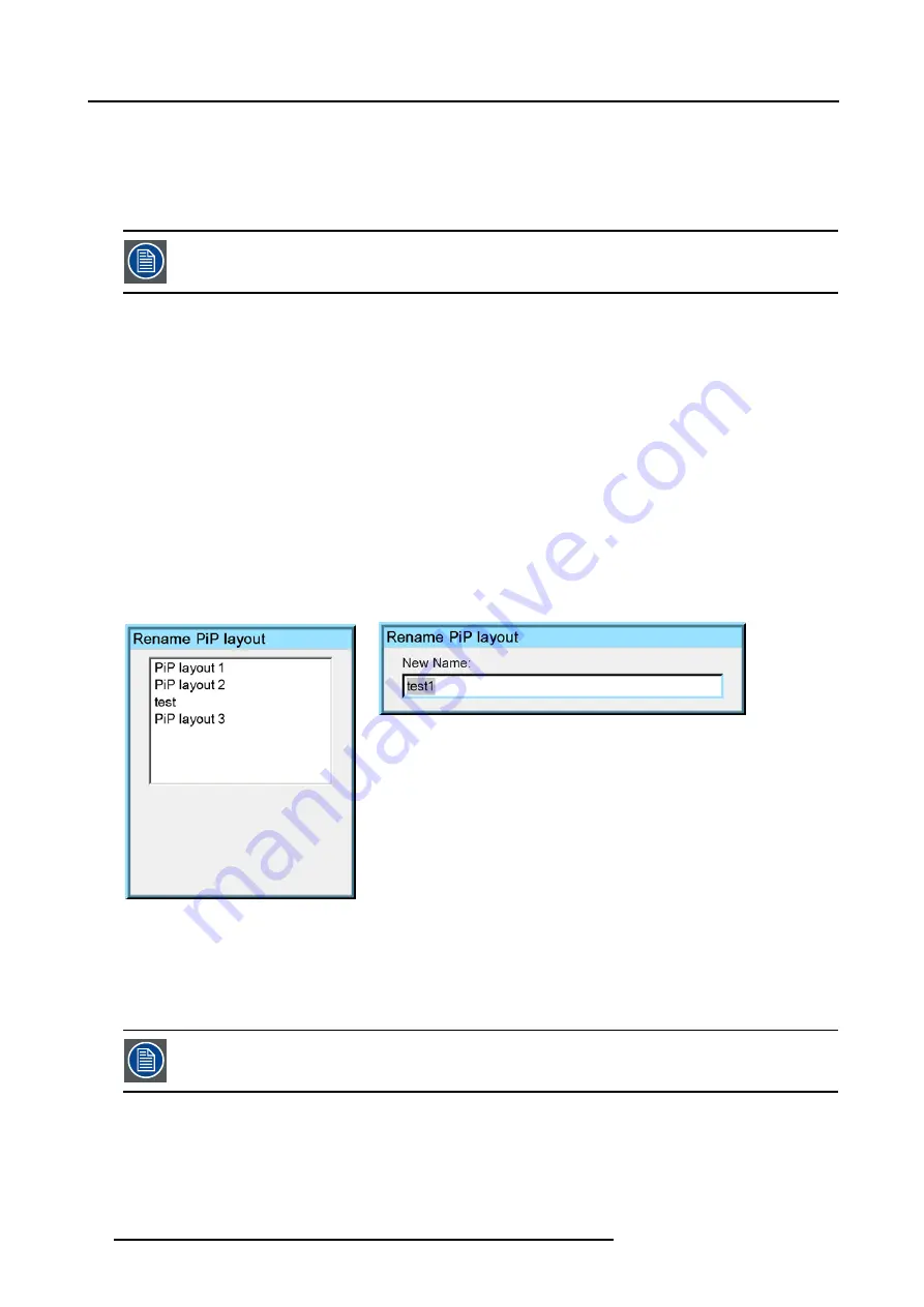
A dialog box is displayed (image 8-12)

8. Use

or

to select the layout to be renamed

9. Press

ENTER

A dialog box is displayed (image 8-13)

Use

or

, the numeric keys on the remote, or the keypad to enter the name and exit with

BACK

or

MENU

.

Image 8-12

Image 8-13

8.5.3

PiP delete layout

What can be done ?

The non fixed layouts (factory and personal layouts) can be deleted.

The fixed layouts and the active layout can not be deleted

How to delete a layout ?

1. Press

MENU

to activate the Tool bar

2. Press

to select the

Tools

item

3. Press

to Pull down the

Tools

menu

80

R5976491 IQ PRO G500 01/02/2007

Summary of Contents for iQ PRO G500

Page 1: ...iQ PRO G500 Owner s Manual R9003081 R5976491 09 01 02 2007...

Page 2: ...3 10 Software version Server version 1 20 Software version Client version 1 20 Barco nv Presentations Noordlaan 5 8520 Kuurne Phone 32 56 36 82 11 Fax 32 56 35 86 51 E mail presentations bid barco com...

Page 3: ...nly to the extent that such activity is expressly permitted by applicable law notwithstanding this limitation SOFTWARE TRANSFER ALLOWED BUT WITH RESTRICTIONS You may permanently transfer rights under...

Page 4: ...s to the SOFTWARE that may be automatically downloaded to your Device Links to Third Party Sites The SOFTWARE may provide you with the ability to link to third party sites through the use of the SOFTW...

Page 5: ...anual may be trademarks registered trademarks or copyrights of their respective holders All brand and product names mentioned in this manual serve as comments or examples and are not to be understood...

Page 6: ......

Page 7: ...25 3 2 9 Extended configuration 25 3 2 9 1 Introduction 25 3 2 9 2 5 cable extended configuration 25 3 2 9 3 S Video extended configuration 26 3 2 9 4 Summarizing 27 4 Getting started 29 4 1 RCU Local...

Page 8: ...R 500 89 10 4 History 90 10 5 Reset runtime 91 10 6 Runtime warning 92 11 Image files menu 95 11 1 Load file 95 11 2 Auto Image 96 11 3 Edit file 97 11 4 Rename file 100 11 5 Copy 101 11 6 Delete 102...

Page 9: ...Zone 151 14 8 1 Dropzone tools 151 14 8 2 Start up 151 14 8 3 File dropping launching 153 14 8 4 Open remotely a file on the projector 155 14 8 5 Remote desktop sharing virtual meeting 155 14 8 6 Drop...

Page 10: ...Table of contents 4 R5976491 IQ PRO G500 01 02 2007...

Page 11: ...unit RCU 2 batteries 2 power cables with outlet plug type CEE7 and ANSI 73 11 1 owners manual 1 safety manual 1 2 Projector Packaging Way of Packaging The projector is packed in a carton box To provid...

Page 12: ...rotection repack your projector as it was originally packed at the factory CAUTION Never transport the projector with the lens mounted on it Always remove the lens before transporting the projector 1...

Page 13: ...1 Packaging and Dimensions 78 305 281 152 487 45 380 Cold air in Length with different lenses see table 20 69 415 Hot air out 565 195 Image 1 3 R5976491 IQ PRO G500 01 02 2007 7...

Page 14: ...ble with cable basket Remarks SVD 2 2 5 1 545mm YES Length with cable basket 565mm QVD 1 3 1 8 1 600mm YES QVD 1 9 2 6 1 590mm YES QVD 3 0 6 0 1 620mm YES QVD 0 85 1 545mm NO QVD 7 0 1 540mm YES Lengt...

Page 15: ...o not install the projection system in a site near heat sources such as radiators or air ducts or in a place subject to direct sunlight excessive dust or humidity Be aware that room heat rises to the...

Page 16: ...ens the wash out becomes more important As a general rule darken the room to the point where there is just sufficient light to read or write comfortably Spot lighting is desirable for illuminating sma...

Page 17: ...2 Installation Guidelines 1 2 3 4 Image 2 1 R5976491 IQ PRO G500 01 02 2007 11...

Page 18: ...the projector P PD x F a b c S S B SH SW SH SW F CD SH 2 B A A front plate Image 2 2 ON Axis installation a side view b top view c back view x optical axis projection lens p projector s screen F floo...

Page 19: ...view x optical axis projection lens p projector s screen F floor CAUTION Only for iQ Pro The harddisk in the IQ Pro server is formatted in horizontal position but can operate in all axes 6 directions...

Page 20: ...The following lenses are available or will become available contact a BARCO service center as an option Lenses Standard version QVD 0 85 1 R9841220 QVD 1 3 1 8 1 R9840950 QVD 1 9 2 6 1 R9840960 QVD 3...

Page 21: ...0 005 SW PD 0 51 6 35xSW 8 35 SW SVD 2 0 2 5 1 PDmin 0 139 1 733xSW 0 1 SW PDmax 0 005 2 224xSW 0 00862 SW PDmin 5 47 1 733xSW 153 SW PDmax 0 2 2 224xSW 13 3 SW Lens program to calculate the projector...

Page 22: ...2 4 4 Removing the lens How to remove the lens 1 Slide the lens door to the left 2 Unlock the lens by pulling the handle located on the right side of the projector image 2 7 3 Remove the lens out of...

Page 23: ...her an open room or lab coat pocket as doing so can contaminate the cloth 4 If smears occur when cleaning lenses replace the cloth Smears are the first indication of a dirty cloth CAUTION Do not use f...

Page 24: ...2 Installation Guidelines 18 R5976491 IQ PRO G500 01 02 2007...

Page 25: ...o 240 VAC I 0 Image 3 1 Fuses For continued protection against fire hazard refer replacement to qualified service personnel ask to replace with the same type of fuse 3 2 Input source connection Overvi...

Page 26: ...w 5 cable input composite video component video PR Y PB S Video Digital Visual Input DVI Computer network interface Image 3 2 Source input section the LED s indicate the selection of a signal L1 Layer...

Page 27: ...s 0 7 Vpp 3dB 75 terminated Image 3 4 Component Video In Component Video the term component describes a number 3 of elements that are needed to make up the video picture these components are R Y Y B Y...

Page 28: ...mage file menu 3 2 4 Composite Video Input Composite video connection A Composite video signal is often available on a yellow cinch connector of a Camera VCR or DVD player in this case you will need a...

Page 29: ...S Video4 The selection of this optional input happens the same way as the standard input key 4 3 2 6 Digital Visual Interface DVI input DVI Digital Visual Interface is a display interface developed in...

Page 30: ...input is via the Menu 3 2 7 Computer input Input specification TTL sync input U min 2 0 V RGB input 0 7 Vpp 3dB Image 3 8 What can be connected RGBHV RGSB Composite sync only possible on Green How to...

Page 31: ...the Installation menu 3 2 9 Extended configuration Overview Introduction 5 cable extended configuration S Video extended configuration Summarizing 3 2 9 1 Introduction What can be done The PiP mode a...

Page 32: ...C Image 3 11 Connecting an S Video signal on the R B BNC Image 3 12 Connecting composite Video signals on the 5 cable input Multiple video signals can not be visualized simultaneously since there is o...

Page 33: ...l video input 1 Video R via 1st BNC 2 Video G via 2nd BNC 3 Video B via 3rd BNC 4 Video VS via 5th BNC 5 Video via the standard composite video BNC input 6 Video Y via S Video input 7 Video C via S Vi...

Page 34: ...3 Connections 28 R5976491 IQ PRO G500 01 02 2007...

Page 35: ...projector Digital Zoom Menu structure Using the menu Using the Dialogboxes 4 1 RCU Local keypad How controlling the projector The projector can be controlled by the local keypad or by the remote cont...

Page 36: ...unctions of the remote control are switching between stand by and operational mode switching to pause blanked picture full power for immediate restarting direct access to all connected sources Diagnos...

Page 37: ...E to stop projection for a short time press PAUSE The image disappears but full power is retained for immediate restarting 6 STBY standby button to start projector when the power switch is switched on...

Page 38: ...19 EFFECTS not yet implemented 20 PIP ADJUST allows to select a PiP window and change its configuration on screen 21 RC operating indication lights up when a button on the remote control is pressed Th...

Page 39: ...Lamp runtime indication while running Independently of the lamp mode when the total runtime of an active lamp lamp1 for example is x 30 hours or more a warning message will be displayed Image 4 4 Lamp...

Page 40: ...the projector is shut down standby If the lamp runtime has not been reset the alert message will reappear at the next start up with again 4 minutes countdown time This alert message can be escaped wi...

Page 41: ...chnician 4 6 Quick set up adjustments Overview Quick lens Adjustment Using the RCU 4 6 1 Quick lens Adjustment What can be done For a quick lens set up and image shift use the RCU dedicated keys or th...

Page 42: ...the remote control and the IR sensor How to connect 1 Plug one end of the remote cable in the connector on the bottom of the RCU 2 Plug the other end in the connector in the front panel of the projec...

Page 43: ...ld be separately addressable with an RCU or computer Therefor each projector has its own address Set up an individual Projector Address The set up of a projector address can be done via the software P...

Page 44: ...s key recessed key on the RCU with a pencil All the LED s on the front of the projector go out Then LED1 starts blinking green the number of hundreds After that LED2 starts blinking the number of tens...

Page 45: ...played in the lower part of the screen follow the instructions Use the BACK key to undo the Zoom function Digital Zoom can not be performed on a logo 4 10 Menu structure PC like menustructure The proj...

Page 46: ...menu 1 Use to pull down a menu How to pull down a submenu 1 Use to pull down a submenu How to exit the submenu 1 Press BACK to exit a submenu Press MENU to exit the menu When the menu has been exited...

Page 47: ...s or to select the digit to be changed 3 Press or to increase or decrease the value To confirm the changes always press ENTER Use or to browse between the different fields In some cases an alphanumeri...

Page 48: ...4 Getting started 42 R5976491 IQ PRO G500 01 02 2007...

Page 49: ...s resolution and or aspect ratio the source can be shown in its native resolution or can be re scaled to the projector s resolution the latter case brings of course some loss of quality For more info...

Page 50: ...on green or sync on H is presented on the BNC s This signal is routed to the video circuit and is projected in a Video Window 5 2 Composite Video How to select one of the 7 composite video inputs 1 Pr...

Page 51: ...Select the S Video input when in presence of a video signal also called S VHS signal An S Video signal is available on the Mini Din connector of a camera VCR or DVD player How to select one of the 3 S...

Page 52: ...rd composite video the S Video input extended mode several BNC connections are added and can be selected as video inputs S Video inputs How to display the Video Selector 1 Press MENU to activate the T...

Page 53: ...How to select an input on the Video Selector 1 Use or to browse through the different inputs 2 Press ENTER Use MENU or BACK to exit the Video Selector How to disable the extended Video Selector 1 Use...

Page 54: ...5 Source Selection Image 5 9 48 R5976491 IQ PRO G500 01 02 2007...

Page 55: ...ral menu 4 Use or to select Pause image 6 1 5 Press ENTER to activate the Pause function A brief sound indicates that the shutter has been activated Image 6 1 The image projection can also be interrup...

Page 56: ...lso be disabled How to enable the timer 1 Press MENU to activate the Tool bar 2 Press to select General 3 Press to Pull down the General menu 4 Use or to select Standby Timer image 6 3 5 Press ENTER t...

Page 57: ...signal this can be useful in case of teleconferencing The configuration has to be done in the Audio Setup menu Starting the Audio Setup menu 1 Press MENU to activate the Tool bar 2 Press to select Gen...

Page 58: ...is the fade in out mode the audio switching will also be done using a fade in out effect 6 4 2 Audio Settings Audio Settings 1 Press MENU to activate the Tool bar 2 Press to select General 3 Press to...

Page 59: ...n screen 1 Press MENU to activate the Tool bar 2 Press to select General 3 Press to Pull down the General menu 4 Use or to select Identification image 6 9 5 Press ENTER to activate the function On the...

Page 60: ...6 General Menu Image 6 10 54 R5976491 IQ PRO G500 01 02 2007...

Page 61: ...rightness Color Tint hue Sharpness Gamma Phase Noise reduction What can be done Correct image settings are important for a good image reproduction The image settings are made through a dialog box with...

Page 62: ...he keypad to change the contrast Image 7 3 7 1 2 Brightness Brightness adjustment Adjusting the brightness will affect the dark areas of the image Increase the brightness to lighten up the parts that...

Page 63: ...ress to pull down the menu 6 Use or to select Tint 7 Press ENTER On the screen appears now a sliderbox 8 Use or the numeric keys on the remote or the keypad to change the Tint 7 1 5 Sharpness How to c...

Page 64: ...e reduction How to change the Noise reduction 1 Press MENU to activate the Toolbar 2 Press to select the Image item 3 Press to Pull down the Image menu 4 Use or to select settings 5 Press to pull down...

Page 65: ...s 16 9 2 35 1 Image 7 8 Anamorphic aspect ratios in DVD sources What can be done The aspect ratio setting forces the projector to project an image using a defined aspect ratio 4 3 16 9 5 4 Auto The se...

Page 66: ...urces where the 16 9 setting allows the best reproduction The Auto function calculates an aspect ratio based on the information stored in the image files Selecting Auto in case of a Video source may s...

Page 67: ...ess MENU to activate the Tool bar 2 Press to select Image 3 Press to Pull down the Image menu image 7 11 4 Use or to select Aspect ratio 5 Use open the Aspect ratio menu 6 Use or to select Custom 7 Pr...

Page 68: ...jector the show native resolution function will handle the sources as follows Source Projected image Name Ratio Resolution Ratio Resolution Particularities Reality SXGA Particularities Graphics xga 4...

Page 69: ...urce is higher than the panel resolution use the arrow keys to scroll through the image pan 7 4 Keystone What can be done The Keystone adjustment is used to align the image this can be necessary when...

Page 70: ...set color temperatures Projector white computer 9300 K Video 6500 K Film 5400 K Broadcast 3200 K These calibrated presets can be selected and will provide optimum color tracking the projector allows h...

Page 71: ...tem 3 Press to Pull down the Image menu 4 Use or to select Color temperature 5 Press to pull down the menu 6 Use or to select custom 7 Press ENTER A slider box for the red custom setting is displayed...

Page 72: ...to bad de interlacing Image 7 22 This function may cause undesired effects on standard sources therefore it can be disabled OFF at any time Enabling disabling the filmmode detection 1 Press MENU to a...

Page 73: ...porting signals there is always a risk of deterioration of the information contained in the signals In case of information contained in the amplitude of the signals which is the case of data color sig...

Page 74: ...ve in input balancing is to set the same black level and the same white level for the three colors of a particular input source Black level setting brightness White level setting contrast The same abs...

Page 75: ...age 7 31 8 adjust the blue black level on a minimal value Note this minimal value is not necessary provided that the 2 other colors are not influencing too much the color to be adjusted in fact the ai...

Page 76: ...e level gain on a minimal value Note this minimal value is not necessary provided that the 2 other colors are not influencing too much the color to be adjusted in fact the aim is to minimize the effec...

Page 77: ...e starting the Input Balance procedure generate a signal with dominant white parts Input balance is also available for a component video source under following conditions A component video signal is p...

Page 78: ...e each source has its own input balance 7 9 AGC on Video AGC Automatic Gain Control allows an automatic amplitude gain control of the incoming video signal AGC is only for Video signals Enabling disab...

Page 79: ...n AGC must therefore be disabled The manual gain control must be done on an external pattern with white areas grey scale bar pattern How to set the Manual Gain Control 1 Press MENU to activate the Too...

Page 80: ...7 Image Menu Image 7 38 74 R5976491 IQ PRO G500 01 02 2007...

Page 81: ...hat are the different possibilities within the PiP mode The input section of the IQ projector allows a multitude of combinations of different input signals which may be projected in the 4 windows of t...

Page 82: ...ersonal layouts PiP dedicated buttons PiP Adjust this button allows to focus on one particular window this is shown with a white frame surrounding the selected window A source identification box is di...

Page 83: ...ndow What can be done It is possible to add a window to the existing windows maximum 4 therefore a source must be selected Sources which are already used are non selectable If for instance the PiP lay...

Page 84: ...the Tools item 3 Press to Pull down the Tools menu 4 Use or to select PiP remove window image 8 7 5 Press ENTER In the lower part of the screen appears a wizard image 8 8 The selected window appears s...

Page 85: ...ave a layout 1 Press MENU to activate the Tool bar 2 Press to select the Tools item 3 Press to Pull down the Tools menu 4 Use or to select PiP layout 5 Press to pull down the menu 6 Use or to select P...

Page 86: ...ect Rename 7 Press ENTER A dialog box is displayed image 8 12 8 Use or to select the layout to be renamed 9 Press ENTER A dialog box is displayed image 8 13 Use or the numeric keys on the remote or th...

Page 87: ...to browse through the windows in the active layout a white frame indicates the window which has the focus This way independent settings picture settings are possible for each window This can also be d...

Page 88: ...djust a window in the layout 1 Use the PiP Adjust key or function in the menu to choose the window to be adjusted 2 Press ENTER A wizard bar is displayed in the bottom of the screen Follow the procedu...

Page 89: ...backplane2 fpga backplane3 ADC layer1 ADC layer2 ADC layer3 Serial eeprom DVI layer2 Serial eeprom DVI layer3 Video decoder Video indicator Video Processor Motor driver Lamp driver Device Slave addre...

Page 90: ...8 Tools Menu 84 R5976491 IQ PRO G500 01 02 2007...

Page 91: ...2 Press to select the Signal item 3 Press to Pull down the Signal menu 4 Use or to select Switching mode 5 Press to pull down the menu 6 Use or to select the desired switching mode image 9 1 7 Press...

Page 92: ...s MENU to activate the Toolbar 2 Press to select the Signal item 3 Press to Pull down the Signal menu 4 Use or to select Background 5 Press to pull down the menu 6 Use or to select the desired backgro...

Page 93: ...s How to display the lamp runtimes 1 Press MENU to activate the Toolbar 2 Press to select the Lamp item 3 Press to Pull down the Lamp menu 4 Use or to select Runtimes image 10 1 5 Press ENTER A textbo...

Page 94: ...rrupting the projection The failure is logged and the lamp will never be initialized in the future Image 10 3 Single mode operation switching principle Dual mode Both lamps are working When one lamp f...

Page 95: ...is extended to 3000 hours The choice of the Power mode must be done during the installation of the projector The switching between the 2 modes can only be done 6 times and this only during the first 1...

Page 96: ...ge 10 6 Image 10 7 10 4 History How to view the history 1 Press MENU to activate the Tool bar 2 Press to select the Lamp item 3 Press to Pull down the Lamp menu 4 Use or to select History image 10 8 5...

Page 97: ...me in the iQ iD 1 Press MENU to activate the Tool bar 2 Press to select the Lamp item 3 Press to Pull down the Lamp menu 4 Use or to select Reset runtime 5 Press to pull down the menu 6 Use or to sele...

Page 98: ...is displayed image 10 12 8 Use or the numeric keys on the remote or the keypad to change the serial number of the lamp serial number 0000000 will not be accepted Image 10 12 WARNING Lamp runtime reset...

Page 99: ...Use or to select Runtime warning image 10 13 5 Press ENTER A dialogbox is displayed image 10 14 6 Use or the numeric keys on the remote or the keypad to change the runtime warning setting Image 10 13...

Page 100: ...10 Lamp Menu 94 R5976491 IQ PRO G500 01 02 2007...

Page 101: ...select the Image files item 3 Press to Pull down the Image files menu 4 Use or to select Load image 11 1 5 Press ENTER A dialog box is displayed image 11 2 6 Use or to select the desired file Tip For...

Page 102: ...s several source parameters Total pixels per line Start pixel Phase Contrast Brightness levels Auto Image works only for data images The measure of the total number of pixels per line can be done thro...

Page 103: ...can be done with the Edit file menu The Edit file menu makes it possible to change the settings of the file according to the real settings of the connected source Consult the source specifications bef...

Page 104: ...values confirm with ENTER Note greyed out fields can not be updated total pixels Image 11 5 Image 11 6 Image 11 7 Which items can be adjusted The following items can be adjusted Active horizontal pixe...

Page 105: ...measurement the advanced parameter allows to choose a short or long hold interval A long AGC hold interval eliminates Macrovision disturbances since the AGC is hold during a long interval thus reduci...

Page 106: ...s that an RGB signal is connected to the BNC s PR Y PB must be selected whenever a progressive signal 32 kHz frequency video signal is connected to the BNC s select the source with Data on BNC s in th...

Page 107: ...mage files item 3 Press to Pull down the Image files menu 4 Use or to select copy image 11 15 5 Press ENTER A dialogbox is displayed image 11 16 6 Use or to select the desired file 7 Press ENTER A tex...

Page 108: ...too different of the source to display then edit this file to get the best image 11 6 Delete How to delete a file 1 Press MENU to activate the Tool bar 2 Press to select the Image files item 3 Press...

Page 109: ...The specification for the file to be selected for each input on that layer is done via RS232 see the RS232 User Guide for more information on the Forced file load command to be sent How to set a file...

Page 110: ...11 Image files menu Image 11 20 104 R5976491 IQ PRO G500 01 02 2007...

Page 111: ...able the full screen representation 1 Press MENU to activate the Tool bar 2 Press to select the Display setup item 3 Press to Pull down the Display setup menu 4 Use or to select Full screen representa...

Page 112: ...s the source information windows displayed in the right lower corner of the screen How to enable disable the Textbox 1 Press MENU to activate the Toolbar 2 Press to select the Display setup item 3 Pre...

Page 113: ...the Display setup item 3 Press to Pull down the Display setup menu 4 Use or to select Take screenshot image 12 3 5 Press ENTER A dialog box is displayed Press yes to confirm image 12 4 A text box sho...

Page 114: ...r position menu image 12 7 5 Press ENTER 6 Use or to position the menu toolbar Image 12 7 12 6 Status bar position What can be done The status bar wizard menu can be centered vertically the range bein...

Page 115: ...ar 2 Press to select the Display setup item 3 Press to Pull down the Display setup menu 4 Use or to select Sliderbox position image 12 9 5 Press ENTER A sliderbox is displayed Use the 4 arrow keys to...

Page 116: ...image works only for data signals How to set up AutoImage 1 Press MENU to activate the Tool bar 2 Press to select the Display setup item 3 Press to Pull down the Display setup menu 4 Use or to select...

Page 117: ...anking is only done on the display i e the setting is not saved in the image file in other words only one type of blanking setting can be done independently of the source How to blank the image 1 Pres...

Page 118: ...ay setup Image 12 14 Image 12 15 Use the checkboxes to enable disable the blanking Use the Reset key to reset the blanking values The logo is also affected by the blanking 112 R5976491 IQ PRO G500 01...

Page 119: ...be adjusted in the installation menu or via the dedicated keys on the remote The following parameters can be adjusted Zoom Focus Shift also for non motorized lenses How to Zoom focus or shift 1 Press...

Page 120: ...es can be programmed Projector address address defined by the user may be from 0 to 255 0 9 is used for RCU communication 0 255 being used for RS232 serial communication Common address address may be...

Page 121: ...mmon address 1 Enter the new projector address with the digit keys on the RCU the local keypad or the cursor keys This address must be between 0 or 1 13 3 Orientation Projector orientations Depending...

Page 122: ...ge 1 Press MENU to activate the Tool bar 2 Press to select the Installation item 3 Press to Pull down the Installation menu 4 Use or to select Language 5 Press to pull down the menu 6 Use or to select...

Page 123: ...the Tool bar 2 Press to select the Installation 3 Press to Pull down the Installation menu 4 Use or to select Quick access keys image 13 9 5 Press ENTER A text box appears on the screen Image 13 9 How...

Page 124: ...s at power resume and recovers the previous settings previous source This function can be disabled if undesired or inadequate for safety reasons etc CAUTION If the Automatic startup function is enable...

Page 125: ...e security mode 1 Press MENU to activate the Tool bar 2 Press to select the installation item 3 Press to Pull down the menu 4 Use or to select Security image 13 12 5 Press to open the menu 6 Use or to...

Page 126: ...How to disable the security mode 1 Press MENU to activate the Tool bar 2 Press to select the installation item 3 Press to Pull down the menu 4 Use or to select Security 5 Press to open the menu 6 Use...

Page 127: ...llation menu 4 Use or to select Change password image 13 17 5 Press ENTER A dialog box is displayed image 13 18 6 Use or the numeric keys on the remote or the keypad to enter and confirm the new passw...

Page 128: ...line for non interlaced sources instead of 0 2 lines for interlaced sources instead of 1 The default setting is NO Never activate this option if not in presence of a Gemini CADWALL system How to enab...

Page 129: ...Web client 14 1 Network architecture SBC Single Board Computer GUI Graphic User Interface Topology The network centric projector iCon and iQPro uses an integrated PC SBC and can be connected to a LAN...

Page 130: ...What can be done The network functionality allows the projector to perform several network functions thanks to network features which are required in most corporate environments Control Management wir...

Page 131: ...Installing the software Start up of the iQ Pro Server Configuring the client software Configuring the Server software The installation of the iQ Pro in a Local Area Network must be done in the same wa...

Page 132: ...board access during pre operating system boot to access BIOS or F8 key to get operating system select menu is only supported on the bottom USB input connector next to the Ethernet connector 3 Use the...

Page 133: ...einstall it from the CD The CD containing the server software and the client tools are delivered with the projector They can always be downloaded from the secured PartnerZone Web site https secure bar...

Page 134: ...F switching on can then happen manually in the general menu or it can be switched on at the same time as the projector Automatic start up How to set the automatic startup 1 Press MENU to activate the...

Page 135: ...on the upper menubar to select the desired sub interface Image 14 7 Control interface IP Internet Protocol The network layer of TCP IP Required for communication with the internet How to add a project...

Page 136: ...ector s IP address must be entered manually Check the operating system on the for the IP address or contact your IT administrator How to add a projector group to the projector group list 1 Click on th...

Page 137: ...active projector Image 14 13 A connected and active projector When connected to a group of projectors some controls may be disabled In general controls will only be selected if this is the status of...

Page 138: ...firmware connection between the projector controller and the single board computer uses fixed IP ad dresses The IP address of the SBC can be found in control panel SBC IP address 192 168 42 51 subnet...

Page 139: ...IQ Network Image 14 16 Image 14 17 CAUTION Leave these IP addresses unchanged The server menu The server menu can be opened by right clicking from the server tray icon R5976491 IQ PRO G500 01 02 2007...

Page 140: ...requests all request are denied Accept all requests automatically desktop sharing is always accepted at the iCon server without prompting for confirmation Notify end of meeting at allows to set a rem...

Page 141: ...he Enable write option allows to enable the client to overwrite projector settings via SNMP Unchecking this option means that projector settings will only be read Exchange settings This tab allows to...

Page 142: ...ocu ment present When using a password the control via the previous V1 1 client version will not be possible therefore disable password protection Note that using a previous client version in combinat...

Page 143: ...e remote communication may then happen over a LAN image 14 26 The projector performs the role of Server while the PC acts as a Client within the system The control and management client software incud...

Page 144: ...tool bar in the upper part of the control interface The active sub screen is indicated with a blue spot 14 5 3 General What can be done Basic controlling monitoring and general parameter setting of t...

Page 145: ...re only grey or green nodes no orange detected On start up a green node will be shown when all projectors are playing the same source type Grey will be shown when some of the projectors are not showin...

Page 146: ...lready contains 4 window it will be impossible to add a new one In that case a window is displayed image 14 32 A dialog box is displayed showing the possible sources to be added image 14 33 3 Select t...

Page 147: ...mage 14 33 Add window dialog box Image 14 34 Importing exporting a layout Every PiP layout can be exported and saved as backup on the network or on the hard disk of the Client PC It can then be import...

Page 148: ...n the import button A dialog box is displayed image 14 36 2 Select the layout to be imported Image 14 36 For more information on Picture in Picture see the PiP chapter 14 5 6 Image settings What can b...

Page 149: ...de Color temperature preset settings 1 Click on Image settings menu in the tool bar to drop down the submenu 2 Click on color temp image 14 37 3 Click on the desired preset color temperature image 14...

Page 150: ...ialog box is displayed image 14 42 3 Use the buttons to zoom or pan Tip Use the buttons to choose small medium or large adjustment steps Each click changes the setting 4 Click on the desired aspect ra...

Page 151: ...ns to shift zoom focus the lens image 14 44 Tip Use the buttons to choose small medium or large adjustment steps Each click changes the setting Image 14 43 the Advanced control submenu Image 14 44 14...

Page 152: ...image 14 46 2 Click on Apply to perform AutoImage Image 14 46 Lamp runtime warnings startup settings 1 Fill in the lamp runtime warning time image 14 47 2 Click on startup screen to enable the startup...

Page 153: ...al parameters as type serial number embedded SW version advanced diagnostics of the projector on board component level fpga decoder user defined critical components by E mail feedback see E mail confi...

Page 154: ...ent advanced content Timing configuration E mail sending can be set to be time dependent or status dependent daily E mail is sent every day the time can be set weekly the day can be set with a calenda...

Page 155: ...ge 14 52 14 7 3 Projector Firmware Upgrade What can be done The client software allows to do an upgrade of the projector s firmware The upgrade is done with a binary file extension bin which is sent t...

Page 156: ...operation image 14 54 5 Press the Upgrade button on the upgrade screen to start the operation The information screen will show the progress of the operation Image 14 53 upgrade interface Image 14 54 I...

Page 157: ...as not yet been declared in the DropZone interface in that case the projector display has to be added to the DropZone list using the Add function 2 The projector display to connect to has already been...

Page 158: ...select an existing projector by its name 1 Click on the three suspension points to open the projector selection dialog box image 14 58 2 Open the listbox and select the projector image 14 60 the loca...

Page 159: ...The projector can then react in different ways depending on the drop mode selected launch file launch file and share store file on the projector File launching Launch files a file stored on the proje...

Page 160: ...the upper button A browser is displayed Choose a file to send to the projector The projector will then process the file according to the setting of the drop mode What to do with the launched files on...

Page 161: ...local PC Besides Desktop sharing one can take the Control mouse and keyboard control over a presentation using NetmeetingTM The control over the presentation can be taken or passed at any time The co...

Page 162: ...Meeting 1 forward control 2 release control 3 request control How to perform remote desktop sharing 1 Click on the middle button The middle button indicates the activation of the remote The desktop is...

Page 163: ...m The desktop can now be remote controlled Image 14 68 The control over the desktop is now done by the local PC However the user can at any time decide to release or forward the control to someone els...

Page 164: ...e Server settings on the Projector allow to configure the DropZone in several ways Disallow new meeting participants New meeting participants will not be able to request desktop sharing or desktop con...

Page 165: ...e web client This may be seen as an alternative to the client software since the main control diagnostic tools are also present Its advantage resides in the fact that no software has to be installed o...

Page 166: ...ilar to the client interface ref Requirements for the use of the Web client Some components have to be installed or enabled on your local client operating system to allow access to the Web client See...

Page 167: ...el under Network Connections This can however be configured automatically if your network uses DHCP 15 2 The Internet and Web services Internet access If you want to access the Internet from the iQ Pr...

Page 168: ...d Outlook To enable control via the Microsoft Exchange integration you need to install enable and configure the IQProEXCH module To enable control from Microsoft Outlook you need to install enable and...

Page 169: ...Install Microsoft Outlook on the Projector Note To be able to access Microsoft Exchange you need a Client Access License Once you have one of those you also have a license to Microsoft Outlook Refer t...

Page 170: ...the TAB General Startup and Type Automatic Make the service use the correct account TAB Log On Select Local System Account Check Allow service to interact with desktop 6 Start the service or reboot th...

Page 171: ...ion page Start Control Panel Internet Options Programs Email You may need to do this as administrator since the service is started as Local System account Tip For more information refer to http www mi...

Page 172: ...layed and a second one is launched the application is not started but the original browser displays the page In this case the second event can not control the browser This is a limitation of the Windo...

Page 173: ...f the application and the starting of the PDF Viewer 4 at 14 30 lauch the PDF file that was stored in step 1 5 5 kill the application and put the projector in standby at 16 00 6 delete the PDF file th...

Page 174: ...one can also add the defined layouts to the drop down list This must be done from Outlook in the menu Tools Forms Design This Form Organizational Forms The administrator should install Organizational...

Page 175: ...r Or display the Folder List and right click the Calendar folder to open the Properties page 2 In the Calendar Properties dialog go to the Forms tab and click the Manage button image A 8 3 On the Form...

Page 176: ...TH presentations to exit at 13 30 This is because Windows uses the same process to display both files and activates them via DDE Image A 11 This is a limitation in the Microsoft Windows ShellExecuteEx...

Page 177: ...crosoft SNMP service must be installed You may need to install this service from the Windows XP CDROM 2 Install the SNMP Agent Extension dll regsvr32 IQProSNMP dll The agent should now be registered a...

Page 178: ...PROJECTORSTATE cooldown READ PROJECTORSTATE textbox READ PROJECTORSTATE projector READ WRITE PAUSE READ WRITE FREEZE READ WRITE PROJECTORRUNTIME READ LAMPWARNINGSTATUS READ LAMPALERTSTATUS READ LAMPMO...

Page 179: ...etting in the iQ Pro Server settings menu The setting should be ON No client server communication in case of a point to point communication IP address is not filled in correctly IP address No client s...

Page 180: ...C Troubleshooting 174 R5976491 IQ PRO G500 01 02 2007...

Page 181: ...p filter 1 2 lamp filter 2 3 x cube filter 4 input filter D 2 Cleaning How to clean the dustfilters 1 Place the projector so as to access easily the filter to be cleaned 2 Push the handle downwards to...

Page 182: ...ned treshold value a warning will be displayed on the screen Image D 7 At that time it is strongly recommended to replace or clean the dustfilter under the X cube Failing to do so will strongly reduce...

Page 183: ...70 1152x864 70 63 800 94 424 1480 1152 912 864 EXGA1_75 1152x864 75 67 499 107 999 1600 1152 900 864 EXGA2_70 1152x864 70 66 098 99 941 1512 1152 945 864 EXGA2_75 1152x864 75 75 199 110 092 1464 1152...

Page 184: ...34 975 31 338 896 640 525 480 MAC_POR 640x870 74 996 68 846 57 280 932 640 918 870 METH_BOOT1 720x400 70 31 500 28 350 900 720 448 400 METH_BOOT2 640x480 59 31 000 24 800 800 640 524 480 MXGA_100 115...

Page 185: ...280 1067 1024 SUNEWS76 1280x1024 76 107 81 130 135 000 1664 1280 1066 1024 SUNXGA60 1024x768 59 984 48 287 64 125 1328 1024 805 768 SUNXGA70 1024x768 70 041 56 596 74 250 1312 1024 808 768 SUNXGA77 10...

Page 186: ...x1600 60 99 404 163 817 1648 1200 1656 1600 VGA_60 640x480 60 31 326 25 061 800 640 525 480 VGA_66 640x480 67 35 100 30 326 864 640 525 480 VGA_72 640x480 73 37 860 31 500 832 640 520 480 VGA_75 640x4...

Page 187: ...63 000 50 000 67 200 1344 1024 796 768 XGA75_GS 1024x768 74 534 59 701 79 284 1328 1024 801 768 SXGA_60 1280x1024 60 63 980 107 997 1688 1280 1066 1024 SXGA _60_2 1400x1050 60 65 574 122 230 1864 1400...

Page 188: ...E Standard Image Files 182 R5976491 IQ PRO G500 01 02 2007...

Page 189: ...y DDWG Digital Display Work Group This connection standard offers two different connectors one with 24 pins that handles digital video signals only and one with 29 pins that handles both digital and a...

Page 190: ...l interface which allows an overview of the different video inputs Composite Video and S Video and whether they are active signal connected or not as well as the selection of these different signals W...

Page 191: ...load 95 rename 100 Filters 175 cleaning 175 location 175 firmware 149 upgrade 149 Full screen representation 105 G Gain 72 73 automatic control 72 manual control 73 Gemini 122 General 50 53 audio 51 A...

Page 192: ...ick access keys 117 RS232 baudrate 118 Sliderbox position 109 Startup screen 105 Take screenshot 106 textbox 106 Lamp menu 87 90 92 history 90 Mode 87 reset runtime 91 Runtime warning 92 runtimes 87 S...

Page 193: ...35 Removing 16 lens 16 RS232 baudrate 118 Runtime 91 92 reset 91 warning 92 S Screenshot 106 security 119 shipped Box 5 content 5 Sliderbox position 109 SNMP 171 installation 171 integration 171 Sourc...

Page 194: ...Index 188 R5976491 IQ PRO G500 01 02 2007...

Page 195: ...rdlaan 5 8520 Kuurne Phone 32 56 36 82 11 Fax 32 56 35 86 51 E mail presentations bid barco com Web www barco com From Date Please correct the following points in this documentation R5976491 09 page w...

Reviews: