background image

7. Step-By-Step Configuration

13.Click

OK

to leave the option menu

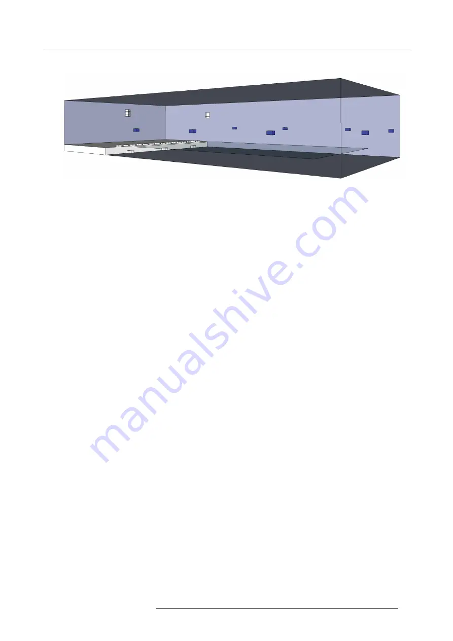
Image 7-2
Simple 3D model of the created loudspeaker setup

7.1.3

Preset Con

fi

guration

7.1.3.1

General Preset Con

fi

guration

To con

fi

gure a preset

1. In the Presets menu, press New and assign a Preset Name, e.g.

Live

-

Click OK to con

fi

rm

2. The view switches to the Preset details tab with a tree structure on the left. In General Loudspeaker Setup select the

fi

le created

before Live and keep Visibility checked

Note:

Ignore the Filtering tab for the time being. This feature is explained in detail in "Filter Creation", page 23. In Devices and
Services the IOSONO CORE should be the used device.

3. In IOSONO CORE move

Processing

,

I/O Control

and

Scene Designer

from

Available Services

to

Used Services

with

<

4. In the tree structure, go to

I/O Control

-

Con

fi

guration

and click

Autodetect

. The displayed con

fi

guration should match your

purchased hardware con

fi

guration with the IOSONO CORE. (E.g.: in case of I/O Con

fi

g M, 1x MADI should be selected) - in

Synchronization choose a suitable setting according to your setup

5. In the tree structure, go to

Processing

-

General

tab and choose in

Buffer Size

128 samples

for low system latency

-

Click

Active

in

Renderer

-

Click

Auto Con

fi

guration

-

OK

the warning dialog

-

Select a

Number of Live Input Channels

according to the number of real inputs from your mixing console

Note:

see "Latency Minimization", page 40 for delay minimization techniques and related trade-offs, for further explanations,
see "Services", page 26.

Note:

Because the loudspeaker

fi

le has 4 loudspeaker groups (Stereo P.A., Near

fi

lls, Surrounds and Subwoofer) the software

creates 4 render slots automatically.

6. Go to the Input Routing tab - make individual routing in the provided matrix if necessary or keep default diagonal line if your live

inputs feed into the

IOSONO CORE

in a linear fashion.

Note:

The rows represent your input signals from the external audio signal source at the physical audio inputs while the columns
represent the virtual sources as renderer input channels.

7. Go to tab

Render Slot 1

-

Select loudspeaker group

Near

fi

lls

-

Select

IOSONO

in

Algorithm Selection

-

In

Settings

keep default selection of

fl

ags

-

Select

Static Scene Rendering

-

Turn

Pre

fi

lter ON

(see "Latency Minimization", page 40 for further explanation of these values and delay minimization tech-

niques and trade-offs.)

-

In Slot Settings uncheck the

Source Trait

dialog

Note:

In

Slot Settings

you may adjust the source latency, minimized source latency and slot gain with regards to the other

render slots. Have the same delay time in all render slots (as automatically set) for the sound to arrive at the same time
at the center of the audience area from all loudspeaker groups. Adjust the delay time of the individual render slots to
exploit the Haas effect in live sound reinforcement.

8. Go to tab

Render Slot 2

R5906746 IOSONO CORE 08/05/2017

35

Summary of Contents for Iosono Core R9801500

Page 1: ...IOSONO CORE Installation And User Manual R9801500 R9801502 R9801503 R9801504 R5906746 00 08 05 2017 ...

Page 2: ...9 361 51143 670 Fax 49 361 51143 677 Support www barco com en support Visit us at the web www barco com Barco NV Beneluxpark 21 8500 Kortrijk Belgium Phone 32 56 23 32 11 Fax 32 56 26 22 62 Support www barco com en support Visit us at the web www barco com Printed in Belgium ...

Page 3: ... fault or provide a replacement at its own discretion within an appropriate period If this measure proves to be impossible or unsuccessful the purchaser can demand a reduction in the purchase price or cancellation of the contract All other claims in particular those relating to compensation for direct or indirect damage and also damage attributed to the operation of software as well as to other se...

Page 4: ......

Page 5: ...nt grant or registration of a utility model or design patent are reserved The manufacturer reserves the right to amend this manual at any time and without notice as result of technical progress This manual is applicable to the IOSONO CORE and the software components Easy Control and Control Unit Read through this manual thoroughly before using the IOSONO CORE in order to avoid mistakes and dangers...

Page 6: ...1 Introduction 2 R5906746 IOSONO CORE 08 05 2017 ...

Page 7: ...evice and in the operating instructions manual Follow all instructions for operation and use Installation The device may only be installed and operated by authorized suitably qualified personal More advanced configurations of the apparatus may only be made by skilled personnel with knowledge of sound technology Place the device on a flat solid and stable surface or fix the device to an appropriate...

Page 8: ...tromagnetic fields like hard disc drives Strong magnetic fields may lead to loss of data or harm the system functionality partly or persistently Do not place the apparatus within the range of strong magnetic fields The manual and the hardware and software components described have been produced according to the currently applicable state of the art Nevertheless the products described are continual...

Page 9: ...t panel Item No Function 1 Power button 2 Volume control 3 Touch screen 3 2 Rear Panel Rear Panel 1 2 3 4 5 6 7 8 9 Image 3 2 IOSONO COREE rear view Number and kind of audio drawers depends on IOSONO CORE configuration For detailed information about connections and available hardware options see Technical Specifications page 59 R5906746 IOSONO CORE 08 05 2017 5 ...

Page 10: ...ntrol and setup the IOSONO CORE with the Control Unit software 3 AUX ethernet port Not used 4 COM port Media control 5 Sync drawer Input and output of different sync signals 6 MADI drawer Electrical and optical MADI input and output connections 7 AES drawer Electrical AES inputs and output connections 8 Blind drawer 9 Power supply Power supply of the IOSONO CORE 6 R5906746 IOSONO CORE 08 05 2017 ...

Page 11: ...es available Deactivate each main power switch if system is unused for longer period of time Always deactivate each main power switch before disconnecting the system from local power circuit Your IOSONO CORE is now ready to be started In order to power on IOSONO CORE please push the power button like shown at Figure 3 1 The power button is now illuminated indicating device is powered and running 4...

Page 12: ...guration using the arrow button in the lower right corner of the Control Client window Use the check boxes to select the reset options you have to complete by entering the randomly generated character string It is recommended to restoring factory settings of your device whenever the IOSONO CORE is not working properly In such case of faulty settings any reset will reload the factory settings or re...

Page 13: ...ed on a USB storage device connected to one of the IOSONO CORE USB ports 6 Network button Enter the network configuration of the Main Ethernet Port Activate DHCP by pressing DHCP ON Set a fixed IP address and subnet mask when DHCP is off Reboot the IOSONO CORE to apply changes or press Cancel to restore the previous configuration 7 Preset selection list Preset buttons are labeled with the name of ...

Page 14: ...4 System Startup 10 R5906746 IOSONO CORE 08 05 2017 ...

Page 15: ...o execute the rendering process It has to reflect the real loudspeaker setup as closely as possible Any deviation between the actual physical setup and the file will impair the rendering precision and the overall sound quality In this section we will describe how to create a loudspeaker file with example values To create a loudspeaker file for your actual setup you need to use real data Step By St...

Page 16: ...nding order based on their average height information 11 The 3D ls file is displayed in layers at Options menu left top view right file name Choose the layer to be displayed using the drop down menu Loudspeaker Group Figure 5 5 visualizes the loudspeaker setup previously created with the Setup Designer image 5 5 12 Define Zones to ensure correct reproduction of zone objects the corresponding zones...

Page 17: ...5 Initial System Configuration 14 Press OK to leave the Options menu Image 5 2 Create Loudspeaker Setup view Image 5 3 Create a rectangular group R5906746 IOSONO CORE 08 05 2017 13 ...

Page 18: ...group Image 5 5 Simple 3D model of a created loudspeaker setup 5 3 Create A Test Preset 5 3 1 Noise About In this chapter a new preset will be created as preparation for running a line check to all connected signal components 14 R5906746 IOSONO CORE 08 05 2017 ...

Page 19: ...ith an individual color The columns represent physical audio outputs of the processor which can be accessed at the rear of your IOSONO CORE hardware You may configure your individual output routing here In our example speakers 1 15 in render slot 1 are connected to outputs 1 15 dummy speakers 16 and 17 require no connection to physical audio outputs speakers 1 4 in render slot 2 are connected to o...

Page 20: ...5 Initial System Configuration Click Stop in upper left corner of main window Image 5 6 Processing settings noise Image 5 7 Audo I O Control status view 16 R5906746 IOSONO CORE 08 05 2017 ...

Page 21: ...con and then click Play image 5 8 Note The run time and total time of the selected WAV file is displayed as well as a cursor moving along a timeline 7 Go to Scene Designer in the tree structure on the left Turn up the volume by holding in the top right corner of the main window A full range pink noise signal becomes audible Note The level meters in I O Control status i Processing and Output will s...

Page 22: ... types need to be compared The actual prefilter s upper frequency value will most likely differ if you are using your own setup If the bass build up is audible a 10 increase of the upper frequency value is a good starting point for this procedure 12 Press Stop in top left corner of the main window Go to Preset tab Preset icon Select the WAV Playback preset and save it Image 5 8 Player status view ...

Page 23: ...5 Initial System Configuration Image 5 9 Scene Designer view Image 5 10 Processing settings Render Slot 1 R5906746 IOSONO CORE 08 05 2017 19 ...

Page 24: ...5 Initial System Configuration 20 R5906746 IOSONO CORE 08 05 2017 ...

Page 25: ...age 6 1 Control Unit Home tab 6 1 2 Preset Structure About To achieve maximum performance without sacrificing flexibility the IOSONO CORE is able to load only the software modules that are necessary for a specific application The set of configuration instructions of the different modules are stored as presets For correct operability the preset configuration must at least contain the following data...

Page 26: ... receives scene data If you have multiple devices in your network that sends scene data for example a CORE and a SAW produc tion PC make sure to separate the data streams by configuring presets with scene ports according to the particular application and scene data sender Visibility Controls whether the preset is visible as a buttons in the Easy Control on the touch display of the IOSONO CORE 6 2 ...

Page 27: ... configuration 2 In the FIR section click on New 3 Enter a name for the new filter and load the impulse response file from the IOSONO CORE s hard drive Note Please see File Transfer page 8 on how to upload files onto the IOSONO CORE 4 Click on New and the new filter will be created from the impulse response To create a new IIR filter inside a preset 1 Click on Preset Details in the tab bar and go ...

Page 28: ... go to Filtering To assign a filter to a speaker inside a filter configuration 1 Go to Filter Library tab and select the desired filter configuration 2 Click on Filter Assignment 3 Select the speaker s to be assigned 4 Select the filter s you want to assign 5 Click on Filter Assignment again to exit filter assignment You can assign a single filter to more than one speaker and more than one filter ...

Page 29: ...ained by the preset in order for it to fulfill the intended task Start by selecting the number of devices you want to use In most cases this is the IOSONO CORE only additional devices like processing extensions can be purchased from Barco To add a device to the device list 1 Go to the Devices and Services in the tree structure on the left in the Preset details tab 2 Select the device you want to u...

Page 30: ...al routing and synchronization options of the IOSONO CORE Typically the configuration of this service is started by automatically selecting the number and type of installed soundcards of the IOSONO CORE by clicking the Autodetect button Further the synchronization source can be selected If Signal is selected as the synchronization source the incoming signal at the primary soundcard will be the det...

Page 31: ...y Step Configuration chapter in Initial System Configu ration page 11that best resembles your type of application 6 2 7 1 Sampleplayer Module About The SamplePlayer module is optional If installed it allows to play back up to 16 imf files in parallel using up to 16 sample slots simultaneously Playback can be controlled independently and simultaneously for all sample slots The SamplePlayer is a mod...

Page 32: ...routing the audio data will be assigned to each source For applications that do not include an external scene sender like the Spatial Audio Workstation or any other kind of OSC device scene data can be generated with the Scene Designer service Each source you create provides the scene data for its corresponding live input channel If you use the Scene Designer make sure to create sources for all yo...

Page 33: ...t_nr_of_pre sets integer Queries presets number controlunit get state state Queries current Control Unit status controlunit set_volume float 60 0dB Defines global volume dB controlunit get_volume float 60 0dB Queries global volume dB controlunit stop_cur rent_preset Stops currently running preset controlunit get_fil ter_configs string presetname string list Queries all available filter configurati...

Page 34: ...nteger Returns list of numbers representing current slot state 0 stopped 1 playing 6 3 2 2 Command Parameter About All available command parameter are described below Please replace the command parameter wildcards by values described parameter Description string ASCII code that is a name string list List of names each name on a separate line integer ASCII code that is an integer float ASCII code t...

Page 35: ...r dialog Uploading and importing presets works in the same fashion When a preset is exported as icp file the complete preset configuration including the loudspeaker file is exported Therefore when you import a preset into a IOSONO CORE the loudspeaker file that comes with the preset is automatically added to the list of loudspeaker setups 6 4 1 Import Export Presets To export a preset to the IOSON...

Page 36: ... the folder where your backup is located and click on Select 6 4 4 Update The Control Unit Software About An update of the Control Unit can either be done from an USB stick or by transferring the update files to the user directory of the IOSONO CORE via the file transfer dialog To update the Control Unit from a USB Stick 1 Copy the respective files to an USB stick and plug it into one of the USB p...

Page 37: ...up consisting of a stereo main PA system a line of nearfill speakers a subwoofer array and multiples single surround speakers To create a loudspeaker file for your actual setup you have to use in real data For further explanations see Create A Loudspeaker File page 11 Nearfill loudspeakers are positioned as a horizontal array along the apron of the stage They are used to provide correct spatial im...

Page 38: ...Rectangle Name your group for example Surrounds Click OK to confirm In Group Type check Independent Dimensions Width 32m Length 50m Height 5m value describes the absolute installation height of the speakers acoustical center above ground Type in Rear Loudspeaker 2 Left Right Spacer 8 50m Left Loudspeakers 3 Left Rear Spacer 10 Click the right speakers will have the same values automatically Note W...

Page 39: ...from your mixing console Note see Latency Minimization page 40 for delay minimization techniques and related trade offs for further explanations see Services page 26 Note Because the loudspeaker file has 4 loudspeaker groups Stereo P A Nearfills Surrounds and Subwoofer the software creates 4 render slots automatically 6 Go to the Input Routing tab make individual routing in the provided matrix if ...

Page 40: ...use the automatically configured diagonal 1 to 1 routing 7 1 3 2 Scene Designer To configure the scene designer 1 In Preset Details go to Scene Designer in the tree structure on the left Create 16 sources by clicking the Add button according to your inputs from the mixing console Name the sources by double clicking on each source s name label in the source list and type in the name with respect to...

Page 41: ...7 Step By Step Configuration Image 7 3 Scene Designer Image 7 4 Scene Designer Image 7 5 R5906746 IOSONO CORE 08 05 2017 37 ...

Page 42: ...ars on the lower right corner in the main window Add another line in filter parameters with Select High Pass from the drop down list in both lines Change the frequency in both lines to for example 150 Hz Change the Q factor in both lines to for example 0 7 image 7 7 Note This filter will have a cut off frequency 6dB at 150Hz with a slope of 24dB Oct 4 Press Filter Assignment to enable filter assig...

Page 43: ...oudspeaker group you wish to assign the LoPass filter to for example the 3 subwoofer icons in the Subwoofers group Click LoPass in IIR Filter List the filters are now assigned to the selected speakers Click Filter Assignment again to disable the assignment mode Note All subwoofers now have an upper cut off frequency at 150Hz to separate them from the full range system components 8 Create a New Fil...

Page 44: ...where possible Use of IOSONO algorithm only possible in groups with sufficient number of loudspeakers Setup design Keep reference point far away from loudspeaker groups Loudspeaker setups may not reflect the reality Keep Buffer Size low 64 128 samples to minimize processing delay Reduce process ing load to allow for small Buffer Size by Preset might not run properly Underruns in complex setups Kee...

Page 45: ...me for this application often is similar to a standard IOSONO setup as described in Hardware Connections page 11 or in the image image 7 9 below Image 7 9 Typical wiring scheme for playback 7 2 2 Create A Loudspeaker File About A loudspeaker file is the basis for any preset and the rendering process It has to reflect the real loudspeaker setup as closely as possible Any deviation between the actua...

Page 46: ... a content file exceed the number of channels configured in the preset the exceeding sources will be muted during playback and a warning message will be displayed 5 In the main window turn down the Volume to inf with the button in the top right corner Click Run in the top left corner Note The button should get a green halo as well as green status lights of I O Control and Processing 6 Go to Proces...

Page 47: ... Mode Select 64 Channels Check Autostart In LTC Input select Audio Input In the main window turn down the Volume to inf with the button in the top right corner Click Run in the top left corner Note If the timecode on the video source is connected to an audio input select Audio Input or if connected directly to the CORE s LTC In select LTC In The number of Channels refers to the maximum number of a...

Page 48: ...e selected file is displayed as well as a cursor moving along a timeline Image 7 11 Player Start timecode 7 2 3 3 DVD Blu Ray Playback with Render About In this chapter the preset will be configured to playback audio content fed from an external DVD Blu Ray Player with a soundtrack in standard 5 1 and being spatially enhanced by the Render algorithm To play back an external source with Render 1 In...

Page 49: ...s represent your input signals from the DVD Blu Ray Player at the audio input of the CORE and the columns represent the input channels to Render in the following order 1 Left 2 Right 3 Center 4 LFE 5 Left Surround 6 Right Surround Keep the soundcard input routing to the renderer to be able to have other input sources in parallel to the 5 1 Render such as mic inputs for announcements or similar Ima...

Page 50: ...ill impair the render precision and the overall sound quality Please find several examples of how to build different loudspeaker files in chapters Create A Loudspeaker File page 11 Create A Loudspeaker File page 41 and Create A Loudspeaker File page 46 To create a loudspeaker file 1 Create a Loudspeaker Setup in System Options Loudspeaker Setups Create Type in Name Screen Size and Position and Aud...

Page 51: ...ed in the Nuendo SAW session If in doubt select the maximum number of 128 channels If the system performance becomes an issue try to limit the number of input channels to the number of audio objects used in the Nuendo SAW session 6 Step through the tabs in Processing and check Input Routing Render Slot settings and Output Routing Note For more information how to select the correct settings for a s...

Page 52: ...7 Step By Step Configuration 48 R5906746 IOSONO CORE 08 05 2017 ...

Page 53: ...uning Extension The System Tuning Extension is an optional feature and is not part of the basic feature set 8 1 Hardware Connections About A wiring scheme of a system setup for acoustical measurements based on the standard setup described in Hardware Connections page 41 is shown below in image 8 1 Image 8 1 Typical wiring of a tuning setup 8 2 Settings To set up the System Tuning Extension 1 To en...

Page 54: ...he Soundcard Inputs 6 Go to Output Routing Create a diagonal line from cell 1 1 in the first loudspeaker group Ring to cell 3 47 in the last loudspeaker group Subwoofer Note In the matrix the rows represent the loudspeakers of your loudspeaker setup that are assigned to render slots each with an individual color The columns represent physical audio outputs of the processor which can be accessed at...

Page 55: ...icrophone positions which have to be distributed evenly The height of the microphone capsule should be at the desired ear height of the future listeners For a seated auditorium a micro phone height of 1 20m for a standing auditorium 1 70m above floor level will work If there are acoustically reflecting objects near the microphones like e g the backrest of an armchair in seated venues the microphon...

Page 56: ...lter Creation About Tuning filters will be designed and applied in the second tab of the System Tuning Extension named Filter Creation Before you can start with the filter design the previously measured data has to be loaded correctly To create a filter 1 In the list right to the graph you can de select loudspeaker groups in column A for Active Only selected loudspeaker groups will be displayed in...

Page 57: ...s that overhang the relevance scope will not be corrected by the filters The relevance scope follows changes of the target curve 7 To add or remove additional filter creation kits press the or buttons When adding a new kit the user may name the Filter Kit and choose to copy settings from other kits image 8 8 Note For maintaining a common target curve but being able to manage differences in relevan...

Page 58: ...8 Advanced System Tuning With The System Tuning Extension Image 8 5 Whitelist Image 8 6 Target curve view Image 8 7 Editing target curve and relevance scope 54 R5906746 IOSONO CORE 08 05 2017 ...

Page 59: ...upper plot shows the frequency response of the filter calculated for the selected speaker and additional speaker or subwoofer filters The target curve can be displayed in both diagrams by checking the Show target curve checkboxes at the right The lower plot can display the measured frequency response of the selected speakers subwoofers as well as the combination of filter and measurement which rep...

Page 60: ...8 Advanced System Tuning With The System Tuning Extension 56 R5906746 IOSONO CORE 08 05 2017 ...

Page 61: ...case you may copy a Filter Configuration that contains the desired FIR filter set change the Loudspeaker Setup and assign the filters to the speakers manually as described in the following steps 3 Select your measured Loudspeaker Group Mark a speaker in the setup display the corresponding filter in the FIR Filter List should be highlighted yellow image 9 2 4 Reassign filters Activate the filter as...

Page 62: ...hange the frequency in both lines to for example 150 Hz Change the Q factor in both lines to for example 0 7 image 9 4 Note This filter will have a cut off frequency 6dB at 150Hz with a slope of 24dB Oct 3 Assign Filters Activate the filter assignment mode by clicking the Filter Assignment button Select loudspeakers for selection of multiple speakers use shift left click in the loudspeaker group y...

Page 63: ...hannels AES EBU input output 1 x Sub D DB 25F with UNC 4 40 per 8 mono input output channels Standard software 2D rendering for loudspeaker setups consisting of one single layer Object based and discrete multi channel audio formats Synchronization via audio input wordclock input and video input Rendering of 128 audio objects simultaneously to all available audio outputs with up to 24 bit 48 kHz So...

Page 64: ...s of 128 per extension Two or more units can be connected to a IOSONO CORE processor which works as the head unit Dimensions W x H x D 485 x 178 x 615 mm 19 x 7 x 24 2 inches Installation depth without connectors 555 mm 21 9 in Weight 20 kg 44 1 lbs Certifications CE KC CCC UL RCM 60 R5906746 IOSONO CORE 08 05 2017 ...

Page 65: ... and recycle them responsibly to promote the sustainable reuse of material resources For more information about recycling of this product please contact your local city office or your municipal waste disposal service For details please visit the Barco website at http www barco com en AboutBarco weee Disposal of batteries in the product This product contains batteries covered by the Directive 2006 ...

Reviews: