background image

4. Daily operation

4.5

OSD menu activation

To activate the OSD menu

1. If not already done so, switch on the display by pressing and holding the stand-by key

for approxi-

mately 3 seconds.

2. Switch on the front key illumination by activating the keyboard (see"Keyboard activation/deactivation",

page 23).

3. Touch the Menu/Enter key

.

As a result, the OSD main menu comes up in the bottom right corner of the screen. If no further actions
are taken within the following 30 seconds, the OSD menu will disappear again.

The time-out of the OSD menu automatic close function can be adjusted or disabled in
the OSD menu (

OSD Time-out

).

The OSD menu position can be adjusted in the OSD menu (

OSD Hor. Pos.

and

OSD Vert.

Pos.

).

4.6

OSD menu navigation

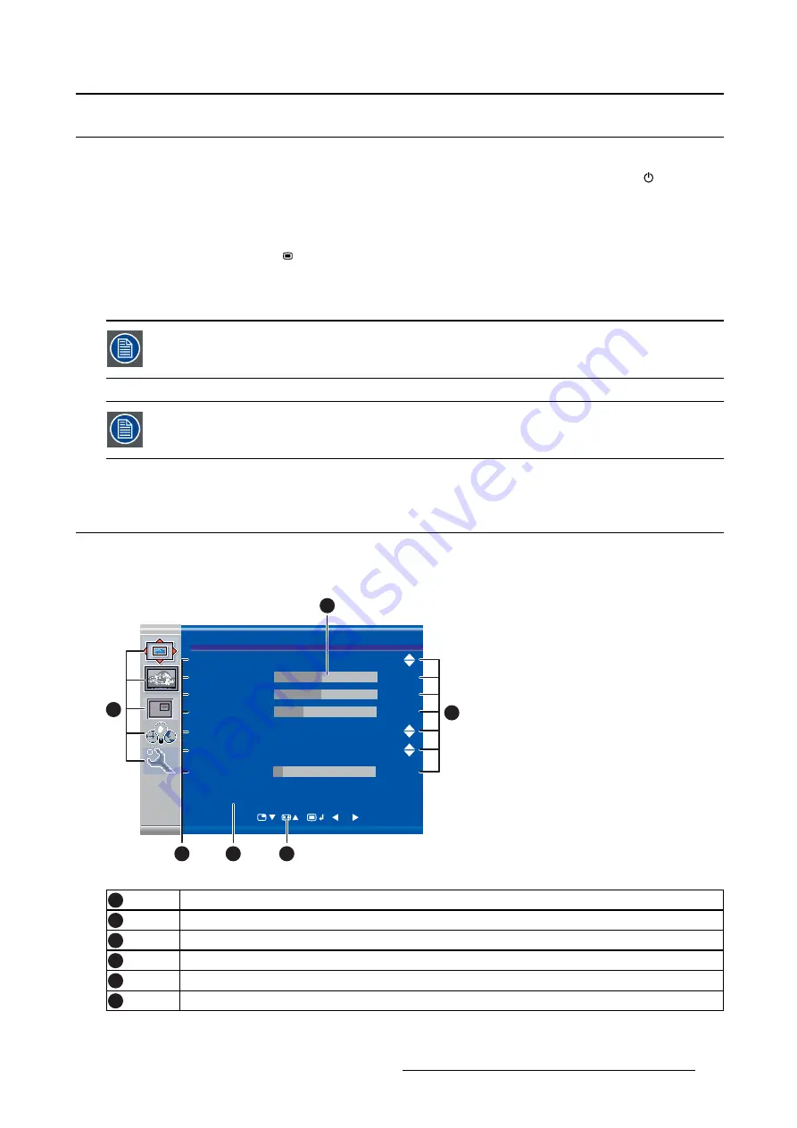
OSD menu structure explained

Below is an example of the OSD menu structure:

Picture

Brightness 


                         50 

Contrast  


                         50

Saturation 


                         30

Profile          


Factory 

Color temperature 

6500K

Gamma 

  Native

Sharpness 


                         10


DVI 1280x800@60Hz

1

6

5

3

2

4

Image 4-1

1

Menu

2

Sub-menu

3

Status bar

4

Legend (shows the functionality associated to each keyboard key)

5

Selector/Slider

6

Item

K5902135 (451920612562) MDSC-2326 01/12/2017

25

Summary of Contents for High Bright MDSC-2326 DDIH

Page 1: ...MDSC 2326 User Guide MDSC 2326 DDIH MDSC 2326 MNAH K5902135 451920612562 01 01 12 2017...

Page 2: ...26 22 62 Support www barco com en support Visit us at the web www barco com Registered address Barco NV President Kennedypark 35 8500 Kortrijk Belgium Phone 32 56 23 32 11 Fax 32 56 26 22 62 Support w...

Page 3: ...MNAH version 17 3 4 Video output connection 18 3 4 1 MDSC 2326 DDIH version 18 3 4 2 MDSC 2326 MNAH version 18 3 5 Nexxis OR 19 3 6 Power supply connection 19 3 7 Cable routing 20 4 Daily operation 23...

Page 4: ...n 43 5 4 2 Language 43 5 4 3 Failover mode 44 5 4 4 Extended keyboard 44 5 4 5 OSD setting 45 5 4 5 1 OSD Horizontal Position 45 5 4 5 2 OSD Vertical Position 45 5 4 5 3 OSD Time out 45 5 4 6 Recall P...

Page 5: ...e consistency It also offers a programmable automated failover feature which ensures that the display automatically switches to a backup source in case the MAIN signal gets lost The display will autom...

Page 6: ...e ideal protection during transport The user guide is available in other languages on www barco com 1 3 About this user guide Overview This manual provides support to the user during the installation...

Page 7: ...stand by key is visible When you touch any of the keys shortly the front illumination of all other keys is switched on for a few seconds When you touch any of these other keys again while the illumin...

Page 8: ...5 Connector compartment cover fixation screw 2 3 Connector view 2 3 1 MDSC 2326 DDIH version Overview 2 3 4 5 10 14 15 16 18 11 9 8 7 6 1 12 13 17 19 Image 2 3 1 DVI 2 2 RS232 3 Input power connector...

Page 9: ...network activity 3 LED1 Green Link is active Off No active network connection 4 LED3 Green Power on normal operation Off System not powered Orange blinking Error 5 Micro USB interface 6 USB 2 0 type A...

Page 10: ...GND 5 Shield 6 24 VDC The ground and the shield connections on the power input connector have no Protec tive Earth function A Protective Earth connection is provided via a dedicated pin see Power supp...

Page 11: ...4 Analog horizontal sync 29 C5 Analog GND return analog R G B 5 VDC output selectable on either pin 14 or 16 via the OSD menu 5V 10 500mA max PC analog VGA input source can be connected to the DVI I i...

Page 12: ...connected 13 Not connected 14 5V input DDC supply 15 GND cable sense 16 Hot plug detect 17 D0_Rx T M D S 18 D0_Rx T M D S 19 GND data 0 shield 20 Not connected 21 Not connected 22 GND clock shield 23...

Page 13: ...detect 17 D0_Rx T M D S 18 D0_Rx T M D S 19 GND data 0 shield 20 Not connected 21 Not connected 22 GND clock shield 23 CK_Rx T M D S 24 CK_Rx T M D S 5 VDC output always available 5V 10 500mA max 2 4...

Page 14: ...nector Overview 19 17 15 13 11 9 7 5 3 1 20 18 16 14 12 10 8 6 4 2 Image 2 12 1 ML_Lane 0 p 2 GND 3 ML_Lane 0 n 4 ML_Lane 1 p 5 GND 6 ML_Lane 1 n 7 ML_Lane 2 p 8 GND 9 ML_Lane 2 n 10 ML_Lane 3 p 11 GN...

Page 15: ...2 Product overview 2 4 9 S Video and S Video out connector Overview Image 2 13 1 Ground Y 2 Ground C 3 Luminance Y 4 Chroma C 5 SG Shielded Ground K5902135 451920612562 MDSC 2326 01 12 2017 13...

Page 16: ...2 Product overview 14 K5902135 451920612562 MDSC 2326 01 12 2017...

Page 17: ...e an arm with suitable safety factor IEC60601 1 To mount the display to an arm stand 1 Attach the arm stand firmly to the panel using the included 4 hexagonal screws M4 x 25 mm and the dented washers...

Page 18: ...able allowing you to view two different video inputs at once Please refer to the dedicated chapter for more info on how to activate and use the PiP and SbS features on your MDSC 2326 This chapter desc...

Page 19: ...is 4 DVI or VGA 5 DisplayPort 6 SDI 1 R G B S 6 7 8 2 R G B SOG 7 8 9 Y Pb Pr 8 9 7 CVBS 3 S Video 10 PC analog VGA input source can be connected to the DVI I input connector using a DVI I to VGA adap...

Page 20: ...one or more of the available video sink s to the corresponding video outputs using the appro priate video cable s SDI 1 2 SDI 2 1 CVBS 3 S Video 4 DVI 1 or DVI 2 5 to be configured in OSD menu see DVI...

Page 21: ...obtain these user guides Nexxis OR is only available on the MDSC 2326 MNAH version 3 6 Power supply connection To connect the power supply 1 Connect the supplied external DC power supply unit to the...

Page 22: ...otential equalization When potential equalization between the display and other devices is required then connect the potential equalization pin POAG DIN42801 to the potential equalization terminal of...

Page 23: ...ion clip from the connector compartment cover and route all cables through it while reinstalling the cover 8b Image 3 10 WARNING When the display is assembled in the medical system take care of the fi...

Page 24: ...3 Display installation 22 K5902135 451920612562 MDSC 2326 01 12 2017...

Page 25: ...ch it remains unlocked As a result its backlight switches off to indicate that the keyboard is locked Keyboard backlight Always on mode When used with keyboard Backlight Always on factory setting is O...

Page 26: ...blinking To minimize the power consumption also the external power supply has to be switched off To switch off your display 1 While your display is switched on unlock the keyboard see OSD menu activa...

Page 27: ...seconds the OSD menu will disappear again The time out of the OSD menu automatic close function can be adjusted or disabled in the OSD menu OSD Time out The OSD menu position can be adjusted in the O...

Page 28: ...ept of shortkey functions is to present a selection of commonly used functions immediately avail able without the need to navigate through the OSD Menu The different available shortkey functions are M...

Page 29: ...ual height Only a subset of multi image configuration settings is available via this shortkey func tion More multi image configuration settings can be selected in the OSD menus When the extended keybo...

Page 30: ...e extended keyboard functions are Main source selection Second source selection Multi image configuration Color temperature selection Image size selection Zoom factor selection Unlike the shortkey fun...

Page 31: ...2 Press the key to switch to the 2nd source quick selection menu 3 Toggle the available second source options by pressing the key corresponding to the desired option If two options are available for...

Page 32: ...t of transfer function settings is available via this quick selection menu More transfer function settings can be selected in the OSD menus 4 8 5 Common Functions Image size selection To quickly selec...

Page 33: ...Image 4 11 4 9 Menu locking unlocking To lock unlock the menu The keyboard can be locked from the Menu to avoid unwanted access to OSD functions When the key board is LOCKED only the OSD Menu key and...

Page 34: ...4 Daily operation 32 K5902135 451920612562 MDSC 2326 01 12 2017...

Page 35: ...3 profile The Factory and X Ray profiles can be temporarily modified but the factory default can t be overwritten and can always be recalled through the recall profile menu item The available profiles...

Page 36: ...icture menu 3 Enter the Contrast submenu The command bar Contrast is highlighted 4 Set the contrast level as desired and confirm 5 1 4 Saturation To adjust the saturation level 1 Bring up the OSD main...

Page 37: ...r To select a color temperature preset 1 Bring up the OSD main menu 2 Navigate to the Picture menu 3 Enter the Color Temperature submenu 4 Select one of the available color temperature presets and con...

Page 38: ...s frame rate is in the range of 50 60 Hz To achieve a minimum latency select one of the surgical modes The available Smart Video presets for your display are Diagnostic best picture quality Surgical l...

Page 39: ...ent This menu item is only available when VGA input is connected About auto adjustment When auto adjustment is activated the phase and clock per line parameters are automatically adjusted To activate...

Page 40: ...llowing this procedure To manually adjust the phase 1 Bring up the OSD main menu 2 Navigate to the Picture advanced menu 3 Enter the Clock Line submenu The command bar Clock Line is highlighted 4 Set...

Page 41: ...Source submenu 4 Select one of the available main source and confirm Note If you selected the Auto Search preset the display will automatically detect the connected signal 5 3 2 Component Mode About...

Page 42: ...atio can be altered Aspect fill the screen on largest dimension no modification in image aspect ratio Native input pixel to LCD pixel mapping no scaling In Aspect and Native the image may be displayed...

Page 43: ...select the 2nd picture mode 1 Bring up the OSD main menu 2 Navigate to the Display Format menu 3 Enter the 2nd Picture Mode submenu 4 Select one of the available 2nd picture modes and confirm Multi im...

Page 44: ...he available 2nd picture sources and confirm 5 3 7 2nd Picture Position About 2nd picture positions The available 2nd picture positions for your display are Top Right Top Left Bottom Right Bottom Left...

Page 45: ...dentification Option SDI SDI module identification Serial Number ANxxxxxxxxxxxx To access information 1 Bring up the OSD main menu 2 Navigate to the Configuration menu 3 Enter the Information submenu...

Page 46: ...unavailable delay required to allow a Nexxis layout change To enable disable failover mode 1 Bring up the OSD main menu 2 Navigate to the Configuration menu 3 Enter the Failover mode submenu 4 Enable...

Page 47: ...ition 1 Bring up the OSD main menu 2 Navigate to the Configuration menu 3 Enter the OSD setting submenu 4 Select OSD Ver Pos The command bar OSD Ver Pos is highlighted 5 Set the OSD vertical position...

Page 48: ...user can modify the default video parameters associated to each profile and save the new parameter settings under the User 1 User 2 or User 3 profile The Factory and X Ray profiles can be modified bu...

Page 49: ...on which the 5V DC supply is applied The available options are Disabled 5V on Pin 14 5V on Pin 16 To select the power on DVI 2 1 Bring up the OSD main menu 2 Navigate to the System menu 3 Enter the P...

Page 50: ...Yes DVI 1 Yes No Yes DVI 2 No Yes Yes SDI 1 No No Yes SDI 2 Yes Yes Yes SDI 2 Other Yes Yes Yes DVI 1 Yes Yes Yes DVI 2 No Yes Yes SDI 1 Yes Yes Yes SDI 2 Yes Yes Yes Other Other Yes Yes Yes MDSC 2326...

Page 51: ...within the following 5 seconds However this behavior can be changed so that the keyboard backlight is always on To adjust the keyboard backlight 1 Bring up the OSD main menu 2 Navigate to the System...

Page 52: ...5 Advanced operation 50 K5902135 451920612562 MDSC 2326 01 12 2017...

Page 53: ...once a year Type of protection Electrical Equipment with external power supply Class I equipment Degree of safety flammable anesthetic mixture Equipment not suitable for use in the presence of a flamm...

Page 54: ...is may result in fire or electric shock Mains lead protection U S Power cord Power cords should be routed so that they are not likely to be walked upon or pinched by items placed upon or against them...

Page 55: ...ipment s power cord from the AC inlet and refer servicing to qualified service techni cians under the following conditions If the power cord or plug is damaged or frayed If liquid has been spilled int...

Page 56: ...to be checked upon collision damage refer to qualified service personnel 6 2 Environmental information Disposal Information Waste Electrical and Electronic Equipment This symbol on the product indicat...

Page 57: ...azardous substances and elements Pb Hg Cd Cr6 PBB PBDE Printed Circuit Assemblies X O O O O O LCD panel X O O O O O External Cables X O O O O O Internal wiring O O O O O O Metal enclosure O O O O O O...

Page 58: ...prevent spreading of infec tions Therefore use of this device in such environments is at the exclusive risk of Customer In case this device is used where potential biological contamination cannot be e...

Page 59: ...e equipment into an outlet on a circuit different from that to which the receiver is connected Consult the dealer or an experienced radio TV technician for help FCC Class A valid for MDSC 2326 MNAH ve...

Page 60: ...and 2 this device must accept any interference received including interfer ence that may cause undesired operation Interference can be determined by turning the equipment off and on If this equipment...

Page 61: ...terruptible power supply or a battery Power frequency 50 60 Hz magnetic field IEC 61000 4 8 30 A m 30 A m Power frequency magnetic fields should be at levels characteristic of a typical location in a...

Page 62: ...o 800MHz d 1 2 P 800MHz to 2 5GHz d 2 3 P 0 01 0 12 0 12 0 23 0 1 0 38 0 38 0 73 1 1 2 1 2 2 3 10 3 8 3 8 7 3 100 12 12 23 At 80 MHz and 800 MHz the separation distance for the higher frequency range...

Page 63: ...4 percent glutaraldehyde solution Sodium hypochlorite bleach 10 percent Green soap USP 0 5 percent Chiorhexidine in 70 percent isopropyl alcohol Like Cleansafe optical cleaning liquid 6 7 Explanation...

Page 64: ...approved according to the EAC regulations Caution Federal law United Stated of America restricts this device to sale by or on the order of a licensed healthcare practitioner Indicates the device is a...

Page 65: ...the device you may find the following symbols nonrestrictive list Indicates a device that can be broken or damaged if not handled carefully when being stored Indicates a device that needs to be prote...

Page 66: ...r use only under the specific terms of a software license agreement between Barco NV or Barco Inc and the licensee No other use duplication or disclosure of a Barco software product in any form is aut...

Page 67: ...2326 MNAH 24VDC 5A MDSC 2326 DDIH 65 W Power consumption nominal from AC mains by the external SKYNET Power Supply Mod BAR A159 MDSC 2326 MNAH 85 W Power save mode Yes Dot clock 165 MHz max DVI OSD la...

Page 68: ...rt Fr Hz Hor Total Vert Total DVI VGA 1 480i 720 x 487 NTSC 15 734 59 94 Y N 2 480p59 720 x 480 480p 31 47 59 94 Y N 3 480p60 720 x 480 480p 31 5 60 Y N 4 576i 720 x 576 PAL I 15 625 50 Y N 5 576p 720...

Page 69: ...VT 1920 x 1200 WUXGA1 74 038 59 95 Y Y 42 IBM 640 x 350 31 5 70 800 449 Y Diag mode 7 N 43 VESA 640 x 350 37 9 85 832 446 Y Y 44 VESA 640 x 400 24 8 56 3 848 440 N Y 45 IBM 640 x 400 31 5 70 0 800 449...

Page 70: ...1280 x 720 720p 37 5 50 Y Y 9 720p59 1280 x 720 720p 44 96 59 94 Y Y 10 720p60 1280 x 720 720p 45 60 Y Y 11 1080i25 1920 x 1080 1080i 28 13 50 Y Y 12 1080i29 1920 x 1080 1080i 33 72 59 94 Y Y 13 1080i...

Page 71: ...product contains software components released under an Open Source license You acknowledge living up to the conditions of each separate Open Source Software license A list of the Open Source Software...

Page 72: ...erms applicability You acknowledge living up to the conditions of each such specific applicable Open Source Software license You are responsible for your own additions changes or modifications without...

Reviews: