

Pattern
to display test patterns
RGB
to toggle colors
Address
to enter projector address
Lens
to open lens adjustments
menu
Pause
to switch to pause
Standby
to switch to standby
Fn
to toggle the display to the
preview image
Auto image
to activate the auto
image adjustment
Digit keys
Direct input selection
or numeric entries
Lens keys
to direct lens adjust-
ment
Settings
Phase:
to adjust phase (analog
signals only)
Sharpness:
to increase edge
detail
Tint:
to adjust tint (NTSC only)
Color:
to adjust color saturation
Brightness:
to adjust the low
lights
Contrast:
to adjust the high lights
Freeze
to freeze the current image
Text
to activate or deactivate the
OSD
Navigation
and
Menu keys
Window
to select the active
window
PiP
to activate selected Picture in
Picture
Info
to activate help information
on a menu item
1
3
4
5
6
2
7
8
9
10
11
12
13
14
15
16
Using the remote control
or local keypad
HDQ series
Quick start guide
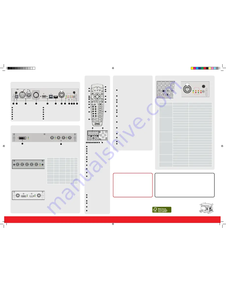
Communication panel
12V /1A
IN
DMX OUT
REMOTE CTRL
RS232/422 IN
USB
10/100 BASE-T
ETH
ACT PWR LMP
10/100 ERR IR ACT
WIFI
SEL
1
2
3
2
3
4
5
6
7
8
11
9
1
12
10
WIFI antenna
for wireless IP (optional)
12V 1A
output
DMX interface
input - output
XLR input
for wired projector control
RS232
for serial communication
USB
backup custom settings
10/100 base-T
for external control over IP and Art-Net
Ethernet status lights
Projector Status lights
WIFI status lights
IR receive
sensor
GSM antenna
input (optional)
1
2
3
4
5
6
7
8
9
10
11
12
MENU
EXIT
ENTER
PAUSE
TEXT
PHASE
TINT
COLOR
BRIGHTN
CONTR
9
0
7
8
5
6
3
4
1
2
LENS
LENS
ZOOM
LENS
SHIFT
LENS
FOCUS
SHARPN
LENS
SHIFT
RG
B
PA
TT
ERN
PI
P
W
IN
DOW
Fn
AU
TO
IMAGE
1 2 3 4 5
6 7 8 9 0
MENU
EXIT
ENTER
RGB
STBY
PAUSE
TEXT
PATTERN WINDOW
PIP
LENS
AUTO
F
N
1
2
3
4
5
6
7
8
9
10
11
12
13
14
15
16
4
7
16
8
15
13
5
1
6
2
9
14
17
Connections
DUAL LINK DVI-I HDCP
INPUT
SEL
SYNC
3G/DUAL HDSDI
OUT1
IN1
IN2
OUT2
SEL
SYNC
SEL
SYNC
R9864000
1
2
•
Dual Link DVI-I HDCP
input accepts:
RGB HV/YUV HV
Single DVI
Dual link DVI
•
3G/DUAL HDSDI
input accepts:
3G : standard SMPTE 425M
HDSDI : standard SMPTE 292M
Dual link : standard SMPTE 372M
SDI : standard SMPTE 259M
BARCO
R/P
R
G/Y/VIDEO
B/P
B
H/S
V/C
R
5-CABLE INPUT
SEL
SYNC
R9864010
Input
R/PR
G/Y/Video
B/PB
H/S
V/CR
RGBHV
R
G
B
H
V
RGBS
R
G
B
S
-
RGSB
R
GS
B
-
-
RGBCV
R
G
B
CV
-
Composite
Video
-
Video
-
-
-
S-Video
-
Y
-
-
C
Component
Video-S
PR/R-Y
Y
PB/B-Y S
-
Component
Video-SOY
PR/R-Y
YS
PB/B-Y -
-
YUV-CV
R-Y
Y
B-Y
CV
-
Optional input
Standard inputs
•
5 Cable Input
accepts:
RGB HV/YUV HV
Composite video
S-Video
3D INPUT
R9864140
3D SYNC IN DISPLAYPORT
HDMI
3D SYNC OUT
SYNC
SEL
SYNC
SEL
BARCO
•
3D Input
accepts:
3D sync in
Display port 1.1a up to 210 MHz
HDMI 1.4a up to 210 MHz
Optional 3D input
10/100 BASE-T
ETH
ACT PWR LMP
10/100 ERR IR ACT
WIFI
SEL
1 2 3 4
6 7 8 9
RGB
STBY
PAUSE
TEXT
PATTERN WINDOW
PIP
AUTO
Button panel
Communication interface
LED or Button
Color status
Description
Standby button
RED
on
Projector is in standby
RED
toggles on/off
Projector startup failed
GREEN
toggles on/off
Projector starts up
GREEN
on
Projector is on
WHITE toggles on/off
Projector goes from/to ECO standby
Pause button
RED
on
Shutter is closed
GREEN
on
Shutter is open
Dimmed WHITE
Shutter is closed, projector in standby
Full WHITE
Shutter is undefined
Full WHITE toggles on/
off
Shutter is closed during reset format-
ter
PWR (power LED)
Off
Projector powers up
RED
Projector is in standby
ORANGE
Projector is in ECO standby
GREEN
Projector is on
LMP (lamp LED)
Off
Lamp is off
RED
No lamp inserted
ORANGE
Lamp is on in ECO mode
GREEN
Lamp is on in normal mode
GREEN
-
ORANGE
Lamp is on in CLO mode
ERR (error LED)
Off
No error
RED
toggles on/off
Error
ORANGE
toggles on/off
Warning
IR
RED
IR signal received
GREEN
IR signal acknowledged
LED and Button indication chart
IMPORTANT:
•
Remove the lens before transporting the projector.
•
Remove lamp house before transporting the projector.
•
To save lamp lifetime, first switch the projector to standby mode and
wait until the after cooling is finished to switch off the main power.
•
Ensure that the projector is operating with clean filters.
•
Do not block the ventilation in and outlets
•
Laser light can cause severe damage to the DMD. This damage is
not covered by warranty.
Printed on FSC certified paper (www.fsc.org)
Quick setup and operation
The following summarizes HDQ setup and operation.
For errorfree installation always refer to the “User and
Installation manual”.
Connect power.
Ensure that the power is properly
connected to the power input sockets.
Y-
Δ
(wye-delta) configuration possible.
Connect available sources
to the appropriate input
terminal.
Switching on.
Turn the mains switch to on.
Start up
sequence starts. Local LCD displays a start
up screen
Standby button
changes from red to green when
pressed.
Image
of the latest selected input appears.
Adjust the lens settings
by pressing the LENS but-
ton or via the direct lens keys on the RCU
Auto image
can load automatically the correct
file. The manual selection can be done via menu or
other control systems.
Orientation
of the unit is set as standard in table
front projection mode. Change the projector set up
in the ALIGNMENT > ORIENTATION menu.
If geometrical distortion occurs
this can be cor-
rected with the Warping settings in the ALIGNMENT
menu.
Tuning the image
can be done in the IMAGE menu
or via the image settings on the RCU
Picture-in-Picture control
can be done in the
LAYOUT menu or via the PiP button.
Lamp
management in the LAMP menu.
Switching off
the unit can be done by pressing the
STBY button for 3 sec. An aftercool up to 300 sec
will start.
1
2
3
4
5
6
7
8
9
10
11
12
13
14
17
WARNINGS
•
Do not cover the lens while projecting
•
Do not look into the lens.
•
Exhaust box becomes very hot when projec-
tor is on.
•
When projector is used in portrait mode,
floor covering can become very hot and
must be resistant to a temperature of 90°C
(194°F)
HDQ-Quickstartguide4.indd 2
9-11-2012 14:22:39


