

WARNINGS
• Do not cover the lens while projecting.
• Do not look into the lens.
• Exhaust box becomes very hot when projector is on.
• When projector is used in portrait mode, floor covering can become very hot and must be resistant
to a temperature of 90°C (194°F)
HDQ series
Quick start guide
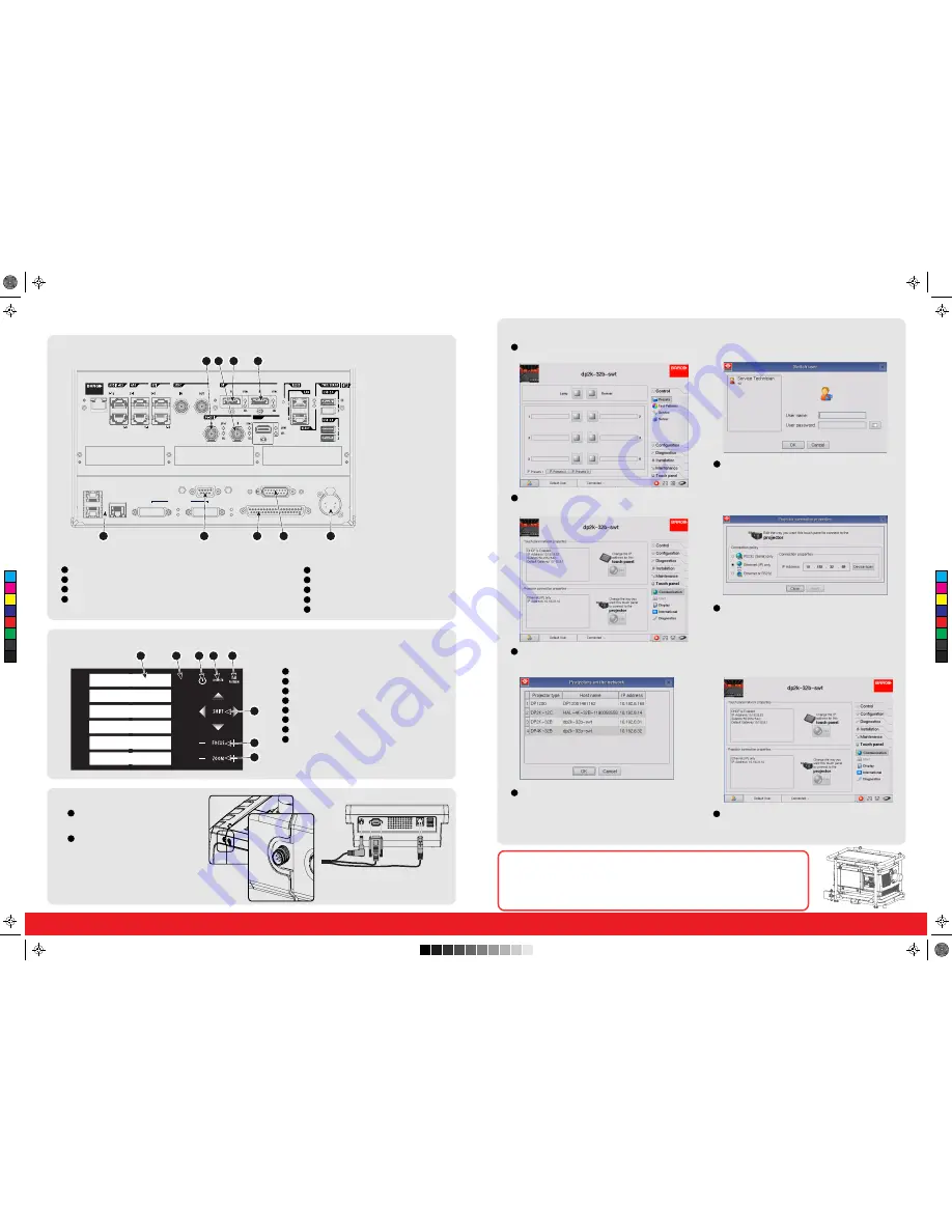
Input & Communication ports
1
2
3
4
GENERAL PURPOSE IN/OUT
DVI A
DVI B
DVI INPUT
SEL
SYNC OK
SEL
SYNC OK
10 / 100 / 1000 BASE-T
RS232 IN
3D INTERFACE
PERIPHERAL PORT
1
2
3
5
6
7
8
9
Input ports:
3G-SDI input: SMPTE 292/424 input, port A
3G-SDI input: SMPTE 292/424 input, port B
DP input, port A, up to 2048x2160@60Hz + HDCP compatible, up to 12bpc
DP input, port B, up to 2048x2160@60Hz + HDCP compatible, up to 12bpc
1
2
3
4
5
6
7
8
9
1
2
3
4
5
6
7
8
1
2
3
4
5
6
7
1
2
1
2
3
4
5
6
1
2
3
4
5
6
7
8
Local keypad
Touch panel connection
Marker area for macro name
Numeric keyboard
Standby key
Dowser open/close button
Test pattern toggle button
Lens shift up/down, left/right
Lens focus
Lens zoom
Communicator Touch Panel
Connect your touch panel as described in the installation instructions. The touch panel starts up with a serial connection. To
speed up the control, an IP connecton is preferred. Connect the touch panel and the projector to an IP network.
Login as Service Technician to set up an IP connection. Click
on User selection icon at the bottom left.
Select Service Technician and enter the password. Click
OK to continue.
Click Touch panel and select Communication.
In projector connection properties, click Edit to open the
network settings.
Enter the IP address or click on Device scan.
The Touch panel’s IP address must be within the same
subnet as the Projector’s IP address in order to make the
communication pssobie. That requires a check of the
Projector’s and Touch panel’s subnet mask setting.
If Device scan was selected, select the desired
projector and click OK.
Connection is made with the projector.
For more information about the use of the Touch panel,
consult the Communicator’s user guide which can be
downloaded from Barco’s web site.
Communication ports:
10/100/1000 base-T
RS232IN
General purpose input/output (GPIO)
3D interface
Peripheral port
Connect the circular plug of the multi
cable with the circular socket at the rear
side of the projector.
Connect the DC plug, the RJ45 Ethernet
plug and the D-SUB plug into their
respective sockets on the touch panel
interface.
C
M
Y
CM
MY
CY
CMY
K
R5905854_00_userguide.pdf 2 1/09/2014 11:04:30


