


Random Access Adjustment Mode
6-7
5976283 BARCOGRAPHICS 808s 160501
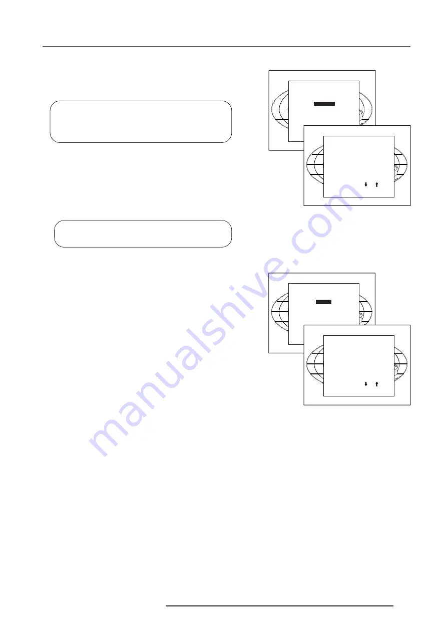
Focusing
Before starting the 'focusing' adjustment, be sure the lenses are
correctly focused.
Push the control disc forward or backward to select 'Focusing' and
press
ENTER
.
Select with or
then <ENTER>
<EXIT> to return.
RANDOM ACCESS
ADJUSTMENT MODE
PICTURE TUNING
GEOMETRY
CONVERGENCE
FOCUSING
COLOR SELECT
ORBITING
CONTR. MODULATION
SOFT EDGE
Select with or
then <ENTER>
<EXIT> to return.
FOCUSING
RED
GREEN
BLUE
BLUE ON SOURCE
ENTER
continues to the Focusing color select menu.
EXIT
returns to Internal Crosshatch Selection or Setup Pattern
Selection menu.
ADJUST
returns to operational mode.
Focusing color select.
The focusing has to be done for the three colors separately.
Therefore, start by selecting Green by pushing the control disc
forward or backward and adjust Midpoint, top, bottom left and right
focusing.
Return to this focusing color select menu and continue with Red and
Blue. Repeat for both colors Midpoint, top, bottom left and right
focusing.
ENTER
selects the focusing menu for the selected color.
EXIT
returns to the Random access main menu.
Midpoint focusing
Push the control disc forward or backward to select midpoint and
press
ENTER
continue with the midpoint focusing.
Adjust by pushing the control disc to the left or to the right until the
center of the image is sharp.
Press
ENTER
to return to the focusing menu.
Top image focusing
The same procedure has to be repeated as for the midpoint focusing.
Push the control disc forward or backward and press
ENTER
to
continue to the top focusing.
Push the control disc to the left or to the right to adjust the top focusing.
Adjust until the upper part of the image is sharp.
ENTER to return to the Green Focusing menu.
Bottom image focusing
The same procedure has to be repeated as for the midpoint focusing.
Push the control disc forward or backward to select bottom and
press
ENTER
to continue to the bottom focusing.
Push the control disc forward or backward to adjust the bottom
focusing. Adjust until the lower part of the image is sharp.
ENTER
to return to the Green Focusing menu.
Left image focusing
The same procedure has to be repeated as for the midpoint focusing.
Push the control disc forward or backward to select LEFT and press
ENTER
to continue to the left focusing.
Push the control disc forward or backward to adjust the left focusing.
Adjust until the left part of the image is sharp.
ENTER
to return to the Green Focusing menu.
Right image focusing
The same procedure has to be repeated as for the midpoint focusing.
Push the control disc forward or backward to select RIGHT and press
ENTER
to continue to the right focusing.
Push the control disc to the left or to the right to adjust the right
focusing. Adjust until the right part of the image is sharp.
ENTER
to return to the Green Focusing menu.
Select with or
then <ENTER>
<EXIT> to return.
FOCUSING
RED
GREEN
BLUE
BLUE ON SOURCE
Select with or
then <ENTER>
<EXIT> to return.
GREEN FOCUSING
MIDPOINT
TOP
BOTTOM
LEFT
RIGHT
When on the Green Focusing menu, press EXIT to return to the
focusing color select menu and continue with the other colors.
Blue on source
After focusing the three color, and a discoloring on a normal image
is still visible, select
'Blue on source'
on the Focusing menu and repeat
the above steps for Midpoint, top, bottom left and right focusing.
Press
EXIT
to return to focusing menu.


