background image

6. Random Access

6.4.5.3

Shift (Windowing)

What can be done with Shift (Windowing)?

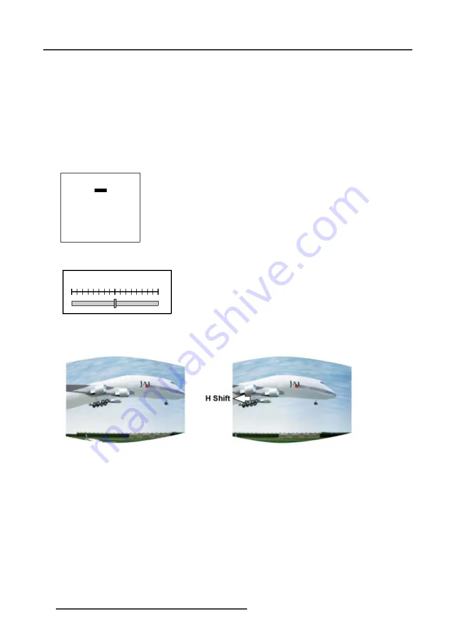
With the Shift function it is possible to shift the image while keeping the pre-distorted WARP 6™ geometry settings of the image.

How to Start Up the Shift adjustment?

1. Push the cursor key

or

to highlight

Shift

(menu 6-45)

2. Press

ENTER

to select.

A barscale indication will be displayed. (image 6-9)

3. Push the cursor key

or

to shift the image horizontally. (image 6-10)

4. Push the cursor key

or

to shift the image vertically. (image 6-11)

WINDOWING

BLANKING

SHIFT

SIZE

GEO SOFT EDGE [ON]

Select with

or

then <ENTER>

<EXIT> to return

Menu 6-45

H SHIFT

0.0

Image 6-9
Horizontal Shift barscale

Image 6-10
Horizontal Shift (Windowing) adjustment

64

R5976698 BARCO GALAXY WARP™ 10 HB 05/04/2004

Summary of Contents for Galaxy WARP 10 HB

Page 1: ...Barco Galaxy WARP 10 HB Owner s Manual R9040330 R5976698 00 05 04 2004...

Page 2: ...ne 1 937 372 7579 Fax 1 937 372 8645 E mail eis barco com Visit us at the web www eis barco com Barco nv Simulation Products Noordlaan 5 B 8520 Kuurne Phone 32 56 36 82 11 Fax 32 56 36 84 86 E mail in...

Page 3: ...sible or unsuccessful the purchaser can demand a reduction in the purchase price or cancellation of the contract All other claims in particular those relating to compensation for direct or indirect da...

Page 4: ......

Page 5: ...ons 23 4 6 1 Linked System 23 4 6 2 RS232 RS422 connection 27 4 6 3 Communication with peripherals 27 4 7 Stereo Connections 27 4 7 1 Single Channel Stereo Connections 27 4 7 1 1 Left Right Phasing Mo...

Page 6: ...7 3 7 Center selection 78 6 5 7 3 8 Center adjustment 78 6 5 7 4 Linearity adjustment 79 6 5 7 4 1 Start up 79 6 5 7 4 2 Horizontal or Vertical Linearity selection 80 6 5 7 4 3 Horizontal Linearity a...

Page 7: ...1 Starting Up 800 Peripheral 125 7 7 2 Defining the Communication Protocol of the RCVDS05 125 7 7 3 COM800 Protocol 126 7 8 Configuration 126 7 9 OSD Color 127 7 10 Internal Patterns 127 8 Service Mo...

Page 8: ...Table of contents 4 R5976698 BARCO GALAXY WARP 10 HB 05 04 2004...

Page 9: ...nsure that nothing can be spilled on or dropped inside the projector If this does happen switch off and unplug the mains supply immediately Do not operate the projector again until it has been checked...

Page 10: ...in a commercial environment This equipment generates uses and can radiate radio frequency energy and if not installed and used in accordance with the instruction manual may cause harmful interference...

Page 11: ...alaxy WARP 10 HB weight 56 kg or 123 5 lbs without lens 1 Remote Control Unit RCU 2 Batteries 1 5V 1 European and 1 American Power Cable 1 Owner s Manual 2 2 Lens Packaging Way of Packaging Lenses are...

Page 12: ...2 Packaging and Dimensions Image 2 2 Left View Dimensions Image 2 3 Top View Dimensions 8 R5976698 BARCO GALAXY WARP 10 HB 05 04 2004...

Page 13: ...free flow of clean air into the projectors ventilation inlets For installations in environments where the projector is subject to airborne contaminants such as that produced by smoke machines or simi...

Page 14: ...where the viewers will be located and go for the highest gain screen possible A high gain screen will provide a brighter picture but reduce the viewing angle For more information about screens contact...

Page 15: ...or when turned with the inputs downwards 3 4 Configuration Which configuration can be used The projector can be installed to project images in four different configurations Front Table Front Ceiling R...

Page 16: ...ront Table CD SH 2 B A A Definitions on the abbreviation on the drawings A Correction value B Distance between floor and bottom of the screen CD Total distance between projector and floor SW Screen Wi...

Page 17: ...d top of the screen CD Total distance between projector and ceiling SW Screen Width SH Screen Height Image height PD Projector Distance distance between screen and projector Image 3 4 Front Ceiling Co...

Page 18: ...box is open this box will not be displayed again till the next alert point is reached Suggestion Lamp runtime is 105 hours It is advisable to adjust the Z axis of the lamp to obtain maximum light outp...

Page 19: ...ION SERVICE Select with or then ENTER EXIT to return Menu 3 2 SERVICE IDENTIFICATION CHANGE PASSWORD CHANGE LANGUAGE CHANGE PROJ ADDRESS SERIAL COMMUNICATION NETWORK LAMP DIMMING MORE Select with or t...

Page 20: ...projector screen distance PD 3 Use the lens formulas to find the best corresponding PD with regard to the measured projector screen distance for the required screen width 3 7 3 Lens formulas Formulas...

Page 21: ...ff from the table Image 3 8 Lens installation Image 3 9 Mounted Lens 3 7 5 Cleaning the lens To minimize the possibility of damaging the optical coating or scratching exposed lens surface we have de v...

Page 22: ...ies delivered The batteries not yet installed to save the battery life time are delivered inside the plastic bag with the power cord How to install 1 Remove the battery cover on the backside of the re...

Page 23: ...on 1 Press the power switch to switch on the projector When 0 is visible the projector is switched off When 1 is visible the projector is switched on The projector starts in standby mode The projector...

Page 24: ...pical or 1000 Maximum hours is dangerous as the lamp could explode Lamp Light Output Indication When starting up the projector the center lumens measurement is performed when the lamp light output is...

Page 25: ...ype Of Input 1 High Bandwidth RGB Input 2 DVI Input1 3 Left Right Phasing Module Table 4 1 Input Facilities 4 5 2 Input 1 Input 1 specifications Input 1 has 5 BNC Input Terminals for 5 Cable Input Whi...

Page 26: ...LECTION AUTOMATIC X SLOT 1 RGB SOG SLOT 2 DVI Select with or ENTER to toggle EXIT to return Menu 4 4 Possible indications on the input slot menu RGS SS CV or HS VS RGB analog signals separate sync is...

Page 27: ...40V or R9827948 110V when using the COM 800 protocol What can be done In a complex multi channel setup projectors can be controlled using the RS232 or COM800 Protocol CLO and Dynacolor can be controll...

Page 28: ...OK IR Green operational Red Stand by IR Reciever Diagnostic Code CTRL 3 CTRL 2 CTRL 1 Null Modem Connector Image 4 4 RS232 Setup How to connect a COM800 Setup Always use the Barco COM 800 Splitter R9...

Page 29: ...Connections 4 5 6 7 8 9 1 2 3 4 5 6 7 8 9 1 Pin Number Pin Number DB9 Female Connector DB9 Female Connector 2 3 Image 4 5 Make a Custom Null Modem Cable R5976698 BARCO GALAXY WARP 10 HB 05 04 2004 25...

Page 30: ...sbefore connecting periphals Sync OK IR Green operational Red Stand by IR Reciever Diagnostic Code CTRL 3 CTRL 2 CTRL 1 Two Way hardwired remote Hardwired remote Hardwired remote 10 100 BASE T RS 232...

Page 31: ...per Video sources and 1 RGB analog or component video source to the projector In addition the audio signal proper to the source can be switched to an audio amplifier Order number R9827890 For more inf...

Page 32: ...nnel Stereo Connections Overview Stereo Set Up Single CADWall Configuration Multiple CADWall Showroom Installation 4 7 2 1 Stereo Set Up How to Set Up the Stereo Parameters The Transport Delay Setting...

Page 33: ...al BNC Connector of the second projector 3 Continue until the Phased L R Signal is connected Looped Through to all the projectors of the Multi Channel Configuration 4 Connect the IR Emitters to a free...

Page 34: ...ors CadWall2 CadWall3 must be set in Forced Asynchronous Mode How to connect the Stereo Signals in a Multiple CADWall Configuration Showroom Installation 1 The Stereo Sync Signal coming from both IG s...

Page 35: ...idth RGB INPUT Projector 4 DVI INPUT L R SIGNAL Phased L R SIGNAL IN OUT G R B H C V High Bandwidth RGB INPUT Projector 5 DVI INPUT L R SIGNAL Phased L R SIGNAL IN OUT G R B H C V High Bandwidth RGB I...

Page 36: ...4 Connections 32 R5976698 BARCO GALAXY WARP 10 HB 05 04 2004...

Page 37: ...rol includes a battery powered infrared IR transmitter that allows the user to control the projector remotely This remote control is used for source selection control adaptation and set up It includes...

Page 38: ...mediate restarting 6 STBY standby button to start projector when the power switch is switched on and to switch off the projector without switching off the power switch Attention Switching to Standby W...

Page 39: ...ew Switching On Switching to standby Switching off Temperature error DMD 5 3 1 Switching On How to switch on 1 Press the power switch to switch on the projector When 0 is visible the projector is swit...

Page 40: ...ff the projector with the power switch 5 3 4 Temperature error DMD Overview When the temperature of one of the DMD is too low or too high the projector will be switched automatically to standby Before...

Page 41: ...ility for the available lenses in a Front Table configuration image 5 5 5 Press EXIT to leave the Quick Lens Adjustment menu LENS ADJUSTMENT ZOOM FOCUS ZOOM with or FOCUS with or ENTER to shift EXIT t...

Page 42: ...S MENU POSITION CENTER 800 PERIPHERAL CONFIGURATION OSD COLOR INTERNAL PATTERNS Select with or then ENTER EXIT to return Menu 5 2 OSD COLOR HIGHLIGHTED ITEM RED GREEN YELLOW Select with or ENTER to ac...

Page 43: ...5 Getting Started Image 5 6 RCU to IR Sensors R5976698 BARCO GALAXY WARP 10 HB 05 04 2004 39...

Page 44: ...ll light up Image 5 7 IR Received Led In case there is IR communication between the RCU and the projector the Green IR Acknowledged Led will light up Image 5 8 IR Acknowledged Led Pointing to the Refl...

Page 45: ...the RCU 2 Plug the other end in the connector in the front panel of the projector labelled CTRL 1 image 5 10 Image 5 10 RCU to Hardwired Remote Input When using the Hardwired Remote Input the IR Senso...

Page 46: ...f other RCU s the Common Address of the projector s can be set to 1 When the projector s RCU is set to address 1 every projector without exception will listen to the commands given by this RCU How to...

Page 47: ...ion How to select the desired input 1 Press the digit key on the RCU corresponding with the desired input Digit Key Type of Input 1 5x BNC Cable Input 2 DVI Input Table 5 3 Input Selection 5 6 5 Pictu...

Page 48: ...ng to room lighting conditions Use the button for a higher contrast Use the button for lower contrast 5 6 6 Menus on Local LCD Display Overview When text is off no menus will be displayed on the proje...

Page 49: ...ccess Overview File Service Load Edit Warp 1 Edit Warp 22 Rename Copy Delete Options o File Sort Name Index o File Load Automatic Manual o Serial File Load On Off Picture Tuning Gamma Input Balance o...

Page 50: ...k Time Forced Asynchronous Yes No 6 2 Starting Up Random Access How to start up Random Access 1 Press ADJUST or ENTER key to start up the Adjustment Mode image 6 1 The Adjustment Mode menu will be dis...

Page 51: ...notation on a menu is built up in different parts Let us have a look to these parts Take the following notation xxxxxxxx eee n ppppXppppi xxxxxxxx base name 8 characters eee file extension first char...

Page 52: ...orting the files 6 3 3 Starting Up File Service How to Start Up File Service 1 Push the cursor key or to highlight File Service menu 6 3 2 Press ENTER to select The File Service menu will be displayed...

Page 53: ...a_60 s01 1 1024x768 xga_60 c01 1 1024x760 xga_60 c02 1 1024x760 xga_60 c03 1 1024x760 Active file xga_60 c04 Select with or ENTER to accept EXIT to return Menu 6 7 CONFIRM LOAD FILE create file xga_60...

Page 54: ...age is projected within this menu it is possible to change the File Settings for the Right Image of a selected source file How to Start Up Edit WARP2 File 1 Push the cursor key or to highlight Edit WA...

Page 55: ...active file they are used to identify the input source file How to find the correct values for the item in the Edit file menu Horizontal Total Pixels If the value for Horizontal Total Pixels is wrong...

Page 56: ...c pulse Use the ENTER key to toggle between leading and trailing Clamp delay The time between the leading edge of the clamp pulse and the locked edge of the sync pulse Can be any value between 0 and 2...

Page 57: ...n be done This item is only available when running in Stereo Mode How to Start Up Edit WARP2 File 1 Push the cursor key or to highlight Edit WARP2 2 Press ENTER to select The Edit file adaptation menu...

Page 58: ...h the cursor key or to highlight Copy menu 6 20 2 Press ENTER to select The Copy selection menu will be displayed menu 6 21 3 Push the cursor key or to select a file name 4 Press ENTER to select The C...

Page 59: ...ction menu will be displayed menu 6 24 3 Push the cursor key or to select a file name 4 Press ENTER to select If ALL is selected your password has to be entered before all files will be deleted A conf...

Page 60: ...on the file name INDEX The files in the list will be sorted on the file extension FILE OPTIONS FILE SORT NAME FILE LOAD AUTOMATIC SERIAL FILE LOAD OFF Select with or ENTER to accept EXIT to return Men...

Page 61: ...F Select with or ENTER to accept EXIT to return Menu 6 29 6 4 Picture Tuning Overview Starting Up Picture Tuning Gamma Input Balance 1 Input Balance 2 Windowing 6 4 1 Starting Up Picture Tuning How to...

Page 62: ...e When a Mono Image is projected within this menu it is possible to adjust the Input Balance of the actual projected source When a Stereo Image is projected within this menu it is possible to adjust t...

Page 63: ...Black Level of the Blue and Red Color until there is 50 noise visible 6 Press EXIT to return to Input Balance menu INPUT BALANCE WHITE BALANCE BLACK BALANCE DEFAULT Select with or then ENTER EXIT to...

Page 64: ...of the Blue and Red Color until there is 50 noise visible 6 Press EXIT to return to Input Balance menu INPUT BALANCE WHITE BALANCE BLACK BALANCE DEFAULT Select with or then ENTER EXIT to return Adjus...

Page 65: ...ve in Steps to be taken see Input Balance 1 page 58 How to Start Up Input Balance 2 1 Push the cursor key or to highlight Input Balance 2 menu 6 37 2 Press ENTER to select The Input Balance menu will...

Page 66: ...geometry settings of the image How to Start Up Windowing Blanking 1 Push the cursor key or to highlight Blanking menu 6 41 2 Press ENTER to select The Blanking menu will be displayed menu 6 42 WINDOWI...

Page 67: ...ing adjustment How to reset the Blanking adjustment s 1 Push the cursor key or to highlight Reset menu 6 44 2 Press ENTER to reset all blanking adjustments BLANKING TOP BOTTOM LEFT RIGHT RESET Select...

Page 68: ...ghlight Shift menu 6 45 2 Press ENTER to select A barscale indication will be displayed image 6 9 3 Push the cursor key or to shift the image horizontally image 6 10 4 Push the cursor key or to shift...

Page 69: ...he cursor key or to highlight Size menu 6 46 2 Press ENTER to select A barscale indication will be displayed image 6 12 3 Push the cursor key or to adjust the horizontal size of the image image 6 13 4...

Page 70: ...ft Edge is default set to On How to change the Geo Soft Edge Setting 1 Push the cursor key or to highlight Geo Soft Edge menu 6 47 2 Press ENTER to toggle Geo Soft Edge OFF or ON WINDOWING BLANKING SH...

Page 71: ...How to Start Up Geometry 1 Push the cursor key or to highlight Geometry menu 6 48 2 Press ENTER to select The Geometry files menu will be displayed menu 6 49 RANDOM ACCESS ADJUSTMENT MODE FILE SERVIC...

Page 72: ...nu 6 51 How to change the Preview setting 1 Push the cursor key to highlight Preview 2 Press ENTER to toggle the Preview mode OFF ON OFF When highlighting a geometry file from the list the geometry ad...

Page 73: ...Random Access 6 5 7 Edit Overview Introduction Start up Coarse Linearity adjustment Fine Shift Transport Delay Blanking Electronic Soft Edge Optional Reset R5976698 BARCO GALAXY WARP 10 HB 05 04 2004...

Page 74: ...ct all grid points underneath Image 6 15 81 grid points Image 6 16 Hierarchic editing structure On top of this hierarchy are the corner grid points when adjusting these grid points all other points un...

Page 75: ...pre distortion set up Coarse linearity adjustment using Side Bows Center selection Center adjustment 6 5 7 3 1 Start up How to Start up the Coarse adjustment 1 Push the cursor key or to highlight Coar...

Page 76: ...y 0 Menu 6 57 Image 6 17 Coarse Corner selections 6 5 7 3 3 Corner adjustment To change a setting only the method using the arrow keys is mentioned in the following procedures the projector will need...

Page 77: ...ny desired corner position image 6 19 Note Apply this procedure to perform a keystone correction this is used to align the image if the projector is mounted at a non standard projector angle image 6 2...

Page 78: ...orrection 6 5 7 3 4 Side Bow selection What can be done With the Coarse Side Bow selection it is possible to apply a bow shaped pre distortion on the projected image perform a coarse linearity adjustm...

Page 79: ...the desired Side Bow The COL ROW Column and Rows indicator will show the corresponding position of the selected Side Bow and an indication box will be displayed on the screen image 6 21 GEOMETRY DISTO...

Page 80: ...re in a similar way to apply the desired bow shaped distortion image 6 22 3 Use the subpixel adjustments to fine shift the selected side bow 4 Continue with the Coarse Side Bow or Center adjustment or...

Page 81: ...to 2 for the Coarse side bow bottom selection This will shift the vertical center line resulting in a coarse horizontal linearity adjustment Follow this procedure in a similar way to shift the horizo...

Page 82: ...col 4 row 4 pixels x 0 y 0 subpixels x 0 y 0 Menu 6 64 Image 6 24 Coarse Center selection 6 5 7 3 8 Center adjustment How to adjust the Center 1 Push the cursor key or to select pixel x 0 in the Geom...

Page 83: ...4 Linearity adjustment Overview Start up Horizontal or Vertical Linearity selection Horizontal Linearity adjustment Vertical Linearity adjustment 6 5 7 4 1 Start up How to Start up the Linearity adjus...

Page 84: ...lines of the hatch pattern are equal or almost equal from left to right 1 Is Horizontal Linearity selected If yes go to step 2 If no Push the cursor key or to highlight Vertical and press ENTER to tog...

Page 85: ...om Access Image 6 27 Horizontal Linearity coarse adjustment Image 6 28 Horizontal Linearity right adjustment Image 6 29 Horizontal Linearity center adjustment R5976698 BARCO GALAXY WARP 10 HB 05 04 20...

Page 86: ...y correction of both sides of the image image 6 30 4 Push the cursor key or to highlight bottom menu 6 73 5 Push the cursor key or to correct the linearity of the bottom side of the image image 6 31 6...

Page 87: ...adjustment 6 5 7 5 Fine Overview Start up Horizontal or Vertical Linearity selection Fine Horizontal or Vertical Linearity adjustment Bow Linearity selection Bow Linearity adjustment Quadrant selectio...

Page 88: ...justment is best done when a hatch pattern is projected on the screen By pressing the key on the RCU an internal hatch pattern is projected instead of the image data How to select the Horizontal or Ve...

Page 89: ...a horizontal way 3 Repeat step 1 to 2 for the Fine hor lin left bottom selection This will result in a fine horizontal linearity adjustment Follow this procedure in a similar way to perform a fine ve...

Page 90: ...l through the available Fine selections until bow lin is displayed menu 6 80 3 Push the cursor key or to select the desired bow linearity point The COL ROW indicator will show the corresponding positi...

Page 91: ...y This will result in a fine bow correction on the projected image Follow this procedure in a similar way to apply a fine bow correction on any desired bow linearity selection image 6 36 3 Use the sub...

Page 92: ...e available Fine selections until quadrant is displayed menu 6 83 3 Push the cursor key or to select the desired quadrant point The COL ROW indicator will show the corresponding position of the select...

Page 93: ...way This will result in a fine adjustment within the selected quadrant Follow this procedure in a similar way to apply a fine adjustment on any desired quadrant image 6 38 3 Use the subpixel adjustmen...

Page 94: ...See menu 6 86 3 Push the cursor key or to select col menu 6 87 4 Push the cursor key or to scroll through all available local grid points within this row An indication box will show the selected loca...

Page 95: ...fine adjustment within the selected local zone Follow this procedure in a similar way to apply a fine adjustment on any desired local zone image 6 40 3 Use the subpixel adjustments to fine shift the s...

Page 96: ...way 3 Push the cursor key or to Pixel y 0 in the Geometry Distortion menu menu 6 92 4 Push the cursor key or to shift the whole image in a vertical way 5 Use the subpixel selections to fine shift the...

Page 97: ...e is described for a system with 3 projectors apply the same guidelines for a multi projector set up 1 Make sure the 3 projectors are set to the default AUTOMATIC Transport Delay mode menu 6 95 Each p...

Page 98: ...ape Start up Blanking Shape selections Blanking adjustment 6 5 7 8 1 Blanking Start up What can be done with Blanking Blanking adjustments affect only the edges of the projected image and are used to...

Page 99: ...nking Shape menu 1 Push the cursor key or to highlight Blanking in the Blanking Soft Edge menu menu 6 103 2 Press ENTER to select The Shape menu will be displayed menu 6 104 BLANKING SOFT EDGE ACTIVE...

Page 100: ...10000 of the total image shape How to adjust the Blanking Shape We assume top left is selected 1 Push the cursor key or to select of image menu 6 106 2 Push the cursor key or to black out the left top...

Page 101: ...s Basic Soft Edge Shape Set up Soft Edge Width Start up Soft Edge Width selections Basic Soft Edge Width Set up 6 5 7 9 1 Introduction When available The Electronic Soft Edge is only available as an o...

Page 102: ...be sure that the following adjustments are done perfectly on all projectors Convergence Electronic Convergence Geometry Color Matching Color Temperature Input Balance Gamma When projecting on a cylind...

Page 103: ...or to highlight Active in the Blanking Soft Edge menu menu 6 109 2 Press ENTER to switch Soft Edge Active OFF to ON menu 6 110 In the default setting Active is set to OFF OFF Soft Edge is disabled ON...

Page 104: ...111 SHAPE top left of image 0 of image 0 Menu 6 112 6 5 7 9 6 Soft Edge Shape selections How the use the Soft Edge Shape selection 1 Push the cursor key or to highlight the first item in the Shape me...

Page 105: ...sic Electronic Soft Edge set up with 2 projectors and a 12 5 overlap zone apply the same procedures for every Electronic Soft Edge you want to create in a multi projector system Image 6 46 Basic Elect...

Page 106: ...0 Menu 6 114 SHAPE right all of image 0 of image 0 Menu 6 115 Image 6 47 Basic Shape set up for Projector 1 Setting up the Shape for Projector 2 1 Use the combination of ENTER and the cursor key or t...

Page 107: ...the cursor key or to highlight Soft Edge menu 6 118 2 Press ENTER to select The Soft Edge Width barscale displaying the width in Range from 00 0 to 25 5 will be displayed image 6 49 BLANKING SOFT EDGE...

Page 108: ...d image 6 51 2 Push the cursor key or to adjust the right width until it matches or exceeds the width of the overlap zone image 6 52 3 Press EXIT to return to the Blanking Soft Edge menu 4 Press EXIT...

Page 109: ...y or to adjust the left width until it matches the right width of projector 1 image 6 54 3 Press EXIT to return to the Blanking Soft Edge menu 4 Press EXIT to return to the Guided Geometry Map menu 5...

Page 110: ...ET Select with or then ENTER EXIT to return Menu 6 119 GEOMETRY RESET COARSE LINEARITY FINE BLANKING SOFT EDGE ALL Select with or then ENTER EXIT to return Menu 6 120 6 5 7 10 2 Coarse Reset How to re...

Page 111: ...to select A warning will be displayed menu 6 126 3 Press ENTER to reset the Fine adjustments Or Press EXIT to return to the Geometry Reset menu GEOMETRY RESET COARSE LINEARITY FINE BLANKING SOFT EDGE...

Page 112: ...lected geometry settings are you sure ENTER to confirm EXIT to return Menu 6 129 6 5 7 10 6 Reset All How to reset the All geometry adjustments 1 Push the cursor key or to highlight All within the Geo...

Page 113: ...R EXIT to return Menu 6 132 RENAME FILE Filename geometry g01 t_bowing t06 t_bowlin t02 t_keyst t03 t_nodist t01 Active file geometry g01 Select with or ENTER to accept EXIT to return Menu 6 133 Chang...

Page 114: ...1 Select with or ENTER to accept EXIT to return Menu 6 136 Changing the characters 1 Push the cursor key or to select the desired character menu 6 137 Or Change that character by pushing the cursor ke...

Page 115: ...synchronous 6 6 1 Starting Up Stereo Options Only available in Stereo Mode The Stereo Options menu is only available when the projector is running in Stereo Mode when a Stereo Source is provided by th...

Page 116: ...justment of 1step or push the or keys for a coarse adjustment of 100 steps Note Adjustment is possible until a full frame delay is reached 4 Press EXIT to return to the Stereo Options menu STEREO OPTI...

Page 117: ...STEREO PHASE INVERT STEREO YES MASTER CHANNEL LEFT STEREO MODE ACTIVE DARK TIME FORCED ASYNCHRONOUS NO WARNING All projectors in the chain must have the same setting for Asynchronous Mode Select with...

Page 118: ...will run in the default Stereo Mode a stereo image is projected PASSIVE The Projector will only display the left or right image of the Stereo Image according to the Master Channel Selection either de...

Page 119: ...ese shutters too late and or opening too early will cause Cross Talk Left Shutter Open O p e n i n g O p e n i n g C l o s i n g C l o s i n g Closed Right Shutter Open Closed DLP Mirrors Active Blank...

Page 120: ...h the cursor key or to highlight Dark Time menu 6 147 2 Press ENTER to select The Dark Time bar scale displaying the width in Range from 0 to 100 will be displayed image 6 61 3 Change the Dark Time Va...

Page 121: ...is achieved by projecting the non moving image in the Asynchronous Mode By using the Forced Asynchronous menu the projector is forced into the Asynchronous Mode giving the best result when projecting...

Page 122: ...6 Random Access 118 R5976698 BARCO GALAXY WARP 10 HB 05 04 2004...

Page 123: ...lation Mode Overview Input Slots No Signal Color Blue Black Shutdown On Off Shutdown Time Lens Zoom Focus Shift Menu Position Center Edges 800 Peripheral Output Module Standard 5 Cable Infrared PPM RC...

Page 124: ...nu picture settings contrast in the center or at the edge of the screen 800 Peripheral to select the type of output module and communication code used in the RCVDS 05 Configuration to set the projecto...

Page 125: ...ipheral indication is made on the menu there are still two possibilities no RCVDS or VS05 connected or RCVDS is switched off When a 800 peripheral is connected to the projector the input slots are not...

Page 126: ...t Shutdown menu 7 8 2 Press ENTER to toggle the Shutdown Setting OFF or ON NO SIGNAL COLOR BLUE SHUTDOWN OFF SHUTDOWN TIME 0 MIN Select with or then ENTER EXIT to return Menu 7 8 7 4 4 Changing the Sh...

Page 127: ...S MENU POSITION CENTER 800 PERIPHERAL CONFIGURATION OSD COLOR INTERNAL PATTERNS Select with or then ENTER EXIT to return Menu 7 10 LENS ADJUSTMENT ZOOM FOCUS SHIFT Select with or ENTER to select EXIT...

Page 128: ...sh the cursor key or to shift the image up or down and or to shift the image left or right 4 Press EXIT to return to the Lens Adjustment menu 5 Press EXIT to return to the Installation menu LENS ADJUS...

Page 129: ...p 800 Peripheral 1 Push the cursor key or to highlight 800 Peripheral menu 7 15 2 Press ENTER to select The 800 Peripheral menu will be displayed menu 7 16 INSTALLATION INPUT SLOTS NO SIGNAL LENS MENU...

Page 130: ...eceived through the RS232 Ports How to change the COM800 Protocol Activation 1 Push the cursor key or to highlight CLO using COM800 NO menu 7 18 2 Press ENTER to toggle between NO or YES 800 PERIPHERA...

Page 131: ...in Red Green Yellow How to change the OSD Color 1 Push the cursor key or to highlight OSD Color menu 7 21 2 Press ENTER to select The OSD color menu will be displayed menu 7 22 3 Push the cursor keys...

Page 132: ...u 7 24 3 Push the cursor key or to select the desired pattern 4 Press ENTER to select The selected pattern will be displayed INSTALLATION INPUT SLOTS NO SIGNAL LENS MENU POSITION CENTER 800 PERIPHERAL...

Page 133: ...n Off Shift Hot Key Text Off Preset Input Balance Warp 1 Preset Input Balance Warp 2 Electronic Convergence Diagnosis I2C Formatter SMPS DynaColor Color Coordinates Exec Linked Dynacolor 8 2 Build up...

Page 134: ...ion Screen What can be seen on the Identification Screen The title page screen shows the general information of the projector The following items will be displayed Type of projector Barco Galaxy WARP...

Page 135: ...he screen The confirm new password is still grayed out 3 Do you want to activate the new password If yes Press ENTER to confirm the new password 4 x characters are displayed in the confirm new passwor...

Page 136: ...he cursor key or to highlight Projector Address menu 8 9 2 Press ENTER to select The actual address is filled in The first digit is highlighted CHANGE PROJECTOR ADDRESS PROJECTOR ADDRESS 6 COMMON ADDR...

Page 137: ...to confirm EXIT to return Menu 8 10 Entering the new Common Address 1 Enter with the digit keys on the RCU or the local keypad Or pushing the cursor key or until the new value is reached Only addresse...

Page 138: ...e 8 8 1 Starting Up the Lamp Menu What can be done All information about the lamp is stored inside the lamp house and can be displayed via the projector software no information can be changed Followin...

Page 139: ...and maintain the CLO setting of this master projector All projectors must have a different projector address between 1 and 12 All projectors must have the same Baudrate The CLO setting of one projecto...

Page 140: ...e EXIT to return Menu 8 16 8 9 Barco Logo 8 9 1 Starting Up Barco Logo What can be done The Barco Logo can be added to the projected image in overlay or on a background on any place on the screen How...

Page 141: ...Y OFF Select with or ENTER to toggle select EXIT to return Menu 8 20 8 9 3 Barco Logo Background How the Change the Barco Logo Background Setting 1 Push the cursor key or to highlight Background menu...

Page 142: ...return Menu 8 23 8 9 5 Hot Key How to Change the Hot Key Setting 1 Push the cursor key or to highlight Hot Key menu 8 24 2 Press ENTER to toggle the Hot Key Setting ON or OFF ON The TEXT key on the R...

Page 143: ...ctor How to Start Up Preset Input Balance 2 1 Push the cursor key or to highlight Preset Input Balance 2 menu 8 27 2 Press ENTER to select The following warning will be displayed menu 8 28 Preset inpu...

Page 144: ...to adjust the Convergence of the projected image 5 Press EXIT to return to the Convergence menu 6 Press EXIT to return to Service menu SERVICE BARCO LOGO PRESET INPUT BALANCE 1 PRESET INPUT BALANCE 2...

Page 145: ...d menu is shown as Following IC s are shown in the I2C info screen Motor Driver Light Sensor Lamp Driver Power Supply Formatter LCD Driver Lamp Module How to display the I2C Diagnosis screen 1 Push th...

Page 146: ...e SMPS Diagnosis screen will be displayed menu 8 38 3 Press EXIT to return to the Service Mode menu DIAGNOSIS I2C FORMATTER SMPS Select with or then ENTER EXIT to return Menu 8 37 SMPS I2C 30H OK AMBI...

Page 147: ...the DynaColor adjustment in the Barco Galaxy WARP 10 HB Image 8 2 Due to the tolerance on optical components the x y values of this color gamut of each projector will differ Image 8 3 When working wit...

Page 148: ...urn Menu 8 39 DYNACOLOR COLOR COORDINATES EXEC LINKED DYNACOLOR Select with or then ENTER EXIT to return Menu 8 40 How to Execute the Linked DynaColor command 1 Push the cursor key or to highlight Exe...

Page 149: ...0 1041 1024 sgi_110v 1280x1024 110 000 114 286 167 160 1464 1280 1038 1024 hp_100v 1280x1024 100 000 108 108 187 488 1728 1280 1085 1024 sxga_96s 1280x1024 96 000 104 000 167 885 1600 1280 1093 1024 s...

Page 150: ...A Standard Source Files 146 R5976698 BARCO GALAXY WARP 10 HB 05 04 2004...

Page 151: ...23 125 Connections 23 Protocol 125 RCVDS05 125 Configuration 11 29 126 Single CADWall 29 Connections 19 21 27 28 36 Communication 27 peripherals 27 Input 21 Power 19 Stereo 27 28 Multi Channel 28 Sing...

Page 152: ...7 Input Balance 58 61 138 1 58 138 Preset 138 2 61 Input Facilities 21 Input Selection 43 Installation 9 120 Guidelines 9 Starting Up 120 Installation Guidelines 9 10 14 16 18 Ambient Temperature 9 Ba...

Page 153: ...ress 42 RCVDS05 23 Connections 23 Reflective Screen 40 Rename 53 File 53 Restricted Access 5 10 Location 5 10 RS232 27 Connection 27 RS422 27 Connection 27 S Safety Area 13 Safety Instructions 5 6 FCC...

Page 154: ...19 35 Switching to standby 20 36 Synchronous 117 Mode 117 T Temperature 9 Ambient 9 Transport Delay 92 W WARP1 49 Edit 49 WARP2 50 Edit 50 Windowing 61 62 Blanking 62 Start Up 62 Z Z axis adjustment...

Page 155: ...oordlaan 5 B 8520 Kuurne Phone 32 56 36 82 11 Fax 32 56 36 84 86 E mail info barco com Web www barco com From Date Please correct the following points in this documentation R5976698 00 page wrong corr...

Reviews: