5. Connections
How to change the input slot setting?
1. Press
ADJUST
or
ENTER
key to start up the Adjustment mode.
2. Push the cursor key
↑
or
↓
to select
Installation
. (menu 5-2)
3. Press
ENTER
.
4. Press the cursor key
↑
or
↓
to select
Input Slots
. (menu 5-3)
5. Press
ENTER
.
The internal system will scan the inputs and displays the result in the
Input Slots
menu.
6. Push the cursor key
↑
or
↓
to select the first or second slot. (menu 5-4)
ADJUSTMENT MODE
Select a path from below :
RANDOM ACCESS
INSTALLATION
SERVICE
Select with
↑
or
↓
then <ENTER>
<EXIT> to return.
Menu 5-2
INSTALLATION
INPUT SLOTS
800 PERIPHERAL
SOURCE SWITCHING
NO SIGNAL
CONVERGENCE
CONFIGURATION
LENS
QUICK ACCESS KEYS
OSD
INTERNAL PATTERNS
Select with
↑
or
↓
then <ENTER>
<EXIT> to return.
Menu 5-3
INPUT SLOTS
1. RGB-SS [CV or HS & VS]
2. RGB-SS [CV or HS & VS]
3. No module
4. No module
______________
1. DVI OUTPUT [Active Image]
Select with
↑
or
↓
then <ENTER>
<EXIT> to return.
Menu 5-4
Possible indications on the input slot menu.
•
RGS-SS [CV or HS&VS] = RGB analog signals, separate sync is composite sync or horizontal and vertical sync.
•
RGB-SS [CV] = RGB analog signals, separate sync is composite video.
•
RGB-SOG [SOG or 3LSOG] = RGB analog signals, sync on green is composite sync or composite tri-level sync.
•
COMPONENT VIDEO - SS [SS or 3LSS] = separate sync is composite sync or composite tri-level sync.
•
COMPONENT VIDEO - SOY [SOY or 3LSOY] = component video with composite sync on Y or composite tri-level sync on Y.
•
DVI
•
VIDEO
•
S-VIDEO.
When changing from an analog signal on the 5 cable module to the DVI input the indication led on the front panel of the module will
switch from the 5 cable input to the DVI input.
5.5.4
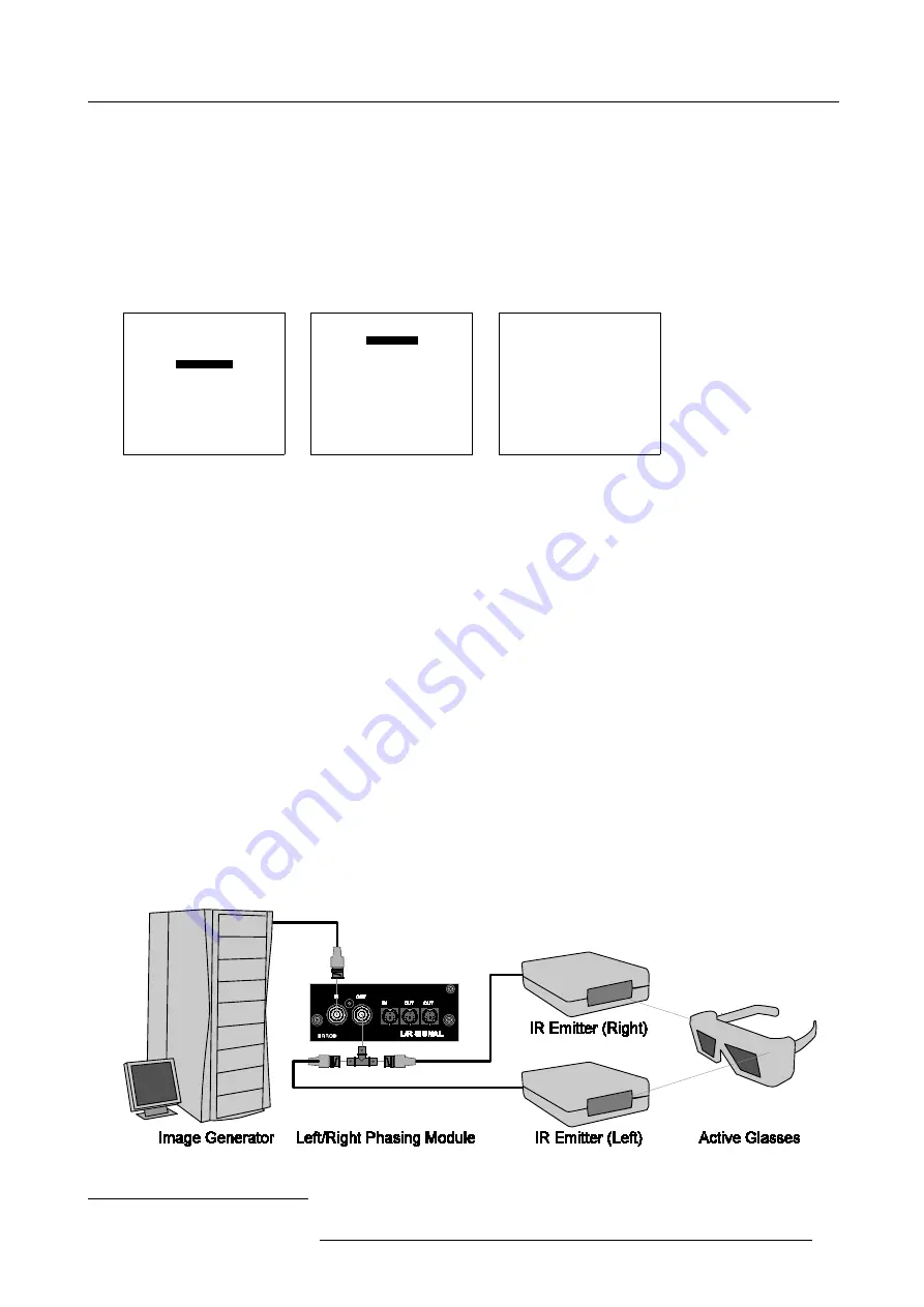
Left/Right Phasing module (Input 3)
Purpose
The Left/Right Phasing module allows us to manipulate the Stereo Emitter Signal that activate the Stereo Glasses.
How to connect the stereo emitter signal ?
1. Connect the stereo emitter signal from the Image Generator to the input (BNC or Mini DIN) of the Left/Right Phasing module.
2. Connect the IR emitters to the output (BNC
2
or Mini DINS) of the Left/Right Phasing module. (image 5-5)
Image 5-5
Left/Right phasing module connections
2. A BNC T-splitter is required.
R5976445 BARCO GALAXY 15042003
25
Summary of Contents for GALAXY R9040310
Page 1: ...SIMULATION PRODUCTS BARCO GALAXY R9040310 R9040311 OWNER S MANUAL 15042003 R5976445 02...
Page 4: ......
Page 8: ...Table of contents 4 R5976445 BARCO GALAXY 15042003...
Page 22: ...3 Installation Guidelines 18 R5976445 BARCO GALAXY 15042003...
Page 90: ...11 Programmable Function Keys 86 R5976445 BARCO GALAXY 15042003...
Page 94: ...A Standard Source set up Files 90 R5976445 BARCO GALAXY 15042003...


