

Event Master E2
– Screen Management System
Quick Start Guide
Input Cards
Output Cards
Expansion Cards
MVR
M2
P/N 26-1205004-00 Rev 01
Ethernet
Genlock
In
Loop
S
D
I
S
D
I
S
D
I
S
D
I
S
D
I
S
D
I
S
D
I
S
D
I
D
V
I
D
V
I
D
V
I
D
V
I
D
P
D
P
H
D
M
I
H
D
M
I
D
P
D
P
H
D
M
I
H
D
M
I
D
P
D
P
H
D
M
I
H
D
M
I
D
P
D
P
H
D
M
I
H
D
M
I
H
D
M
I
H
D
M
I
H
D
M
I
H
D
M
I
S
D
I
S
D
I
S
D
I
S
D
I
H
D
M
I
H
D
M
I
H
D
M
I
H
D
M
I
C
X
P
C
X
P
C
X
P
C
X
P
1
2
3
4
5
6
7
8
9
10
11
12
13
14
H
Dual Redundant Power Supplies
H
1
2
3
4
1
2
S3D
In
S3D
Out
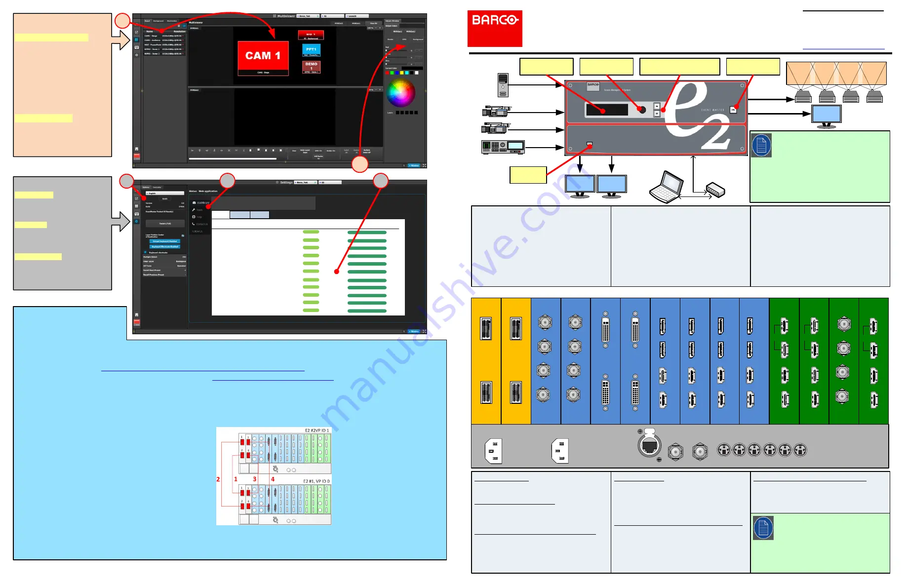
Expansion Cards
- 2 High speed CXP connectors
SDI Input & Output Cards
- 4 SDI BNC connectors
- SD/HD/3G formats (6G ready)
DisplayPort/HDMI Combo Input Cards
- 2 DP and 2 HDMI locking connectors
- Displayport 1.1a specification
- HDMI 1.4a specification
- HDCP 1.4 & EDID 1.3
DVI Input Cards
- 2 DVI-I connectors (no analog signals)
- Single / Dual Link formats
- DVI 1.0 specification
- HDCP 1.4 & EDID 1.3
Quad Channel DisplayPort Output Cards
- 4 full-size DP locking connectors
- Up to 4 independent signals
- DisplayPort 1.2 specification
- HDCP will be supported in a future software
release.
HDMI Output cards (including MVR)
- 4 HDMI connectors (top 2 connectors capable of
high-speed HDMI signals up to 300 MHz)
- HDMI 1.4a specification
- HDCP 1.4 and EDID 1.3
M1
Be sure that you properly align the Link cable connectors prior to insertion.
Connectors should insert easily with almost no resistance, until the lock is
about to engage. Be sure that the lock engages fully to ensure proper
contact. Make sure that you use the locking mechanism and then push
each cable until it locks in place.
1. Connect the Link cables provided with each E2 between the Link
connectors as follows:
• VP ID 0, Link Card slot 1, Link 1 >> VP ID 1, Link Card slot 1, Link 2
• VP ID 0, Link Card slot 1, Link 2 >> VP ID 1, Link Card slot 1, Link 1
• VP ID 0, Link Card slot 2, Link 1 >> VP ID 1, Link Card slot 2, Link 2
• VP ID 0, Link Card slot 2, Link 2 >> VP ID 1, Link Card slot 2, Link 1
4. Start the Event Master Toolset
version 4.0 or higher.
5. Make sure that both E2s are
discovered on the network and that
they have different Unit IDs.
If the system does not discover your
device, you may manually add it. See
"How to manually add a device into
the selected system"
in the user’s
guide.
6. Drop one of the E2s in the EM GUI.
Link Connections
Ethernet switch
PC with Event Master
Control Software
MVR
MVR
Refer to the
Event Master devices User’s
guide
(R5905948) for detailed system
specifications, descriptions and operation
instructions.
Any item contained in this document may
change without notice.
For the latest version of the
Event Master
devices User’s guide
(R5905948) and the
E2
–
Screen Management System Quick Start
Guide
(26-1205004-00), visit www.barco.com.
Power Switch
USB Port
SEL and ESC Buttons
ADJUST Knob
Display
System Setup
1. Ensure that the unit is physically secured in a
rack or is placed on a flat surface with stable
support. If the unit is installed in a rack,
it is
mandatory that the rear brackets are also
installed
.
2. Connect all sources, displays, and peripherals
to the E2
according to your event’s
requirements.
3. Connect AC power to the unit. If power
redundancy is desired, connect power to both
power plugs.
4. Connect to a computer that has the Event
Master control software installed, via an
Ethernet cable. A switch is optional if additional
devices will be connected.
5. Power up the E2, the PC, all monitors and
peripherals.
6. Verify that no error messages appear on the E2
front panel.
7. After the E2 boots up, run the Event Master
control software and follow the sequence of
instructions listed in this Quick Start Guide to
complete the system setup and configuration.
Should the system not fully boot correctly, press
and hold the SEL and ESC buttons while
applying power to the unit. Release these
buttons when a menu appears asking to Factory
Reset the unit. Perform the Factory Reset and
the unit will boot normally.
Dashboard
a quick glance of your E2
Expansion
0
Ready
√ Run Diagnostics
Expansion
1
Ready
√ Run Diagnostics
Input
2
Ready
√ Run Diagnostics
Input
3
Ready
√ Run Diagnostics
Input
4
Ready
√ Run Diagnostics
Input
5
Ready
√ Run Diagnostics
Input
6
Ready
√ Run Diagnostics
Input
7
Ready
√ Run Diagnostics
Input
8
Ready
√ Run Diagnostics
Input
9
Ready
√ Run Diagnostics
Input
10
Ready
√ Run Diagnostics
Expansion
Slot ID
Card Status
Actions
Inputs
Outputs
Other
S1
S2
S3
SETTINGS MENU
S1:
Options - On the Options tab
click on the boxes to select system
wide user preferences such as
Layer positioning.
S2:
Tools - Allows users to
perform Backup and Restore
operations or download the latest
software from the Barco website
S3:
Dashboard - Provides status
information regarding the cards
and other system diagnostic
information.
https://www.barco.com/en/Products/Image-processing/Presentation-switchers
Linking
An Event Master unit can link with other
Event Master units. Depending on the
linking configuration, linked units share
For links to instructional videos, see the Barco Folsom IP YouTube site at:
https://www.youtube.com/user/BarcoFolsomIP.
Notes:
- Input and Output cards each support
one 4K/UHD signal.
- This sample system shows the optional DP 1.2
Output card. The system does not ship with this
card; your configuration may be different.
-
Cards are
not
hot-swappable.
Example: Linking a pair of E2s
1. Check the cable orientation for keying. The cable fits in only one orientation.
2. Fully insert the cable into the connector on the Link Card.
3. If the cable resists full insertion, do not force it; pull the cable out, check its
orientation, and reinsert it.
4. Make sure that the latch is properly engaged.
5. Always use the release when removing the cable.
Improper insertion or removal of Link cables can damage the
connectors and is not covered under the product warranty.
2. Make sure that the E2s have different IP addresses.
The default IP address for each unit is the same; one of them must be
changed.
3. Connect all devices to network Ethernet.
7. Drop the second E2 in the EM GUI.
The EM GUI presents the options of adding the second unit as a new system,
as a master, or a as a slave.
H
D
M
I
H
D
M
I
H
D
M
I
H
D
M
I
H
MULTIVIEWER (MVR)
MENU
M1:
Select MVR Sources - From
the dropdown menus select the
Inputs, Backgrounds, and
Destinations you want to view
and drop them into Multiviewer
Outputs. Overlapping is not
allowed. An MVR source may be
used twice. A maximum total of
63 windows can be used for
Inputs and 63 windows can be
used for Outputs.
M2:
Adjust Window - Adjust the
size, position and the color
parameters associated with each
window. Repeat for all Inputs and
save.


