background image

R5906848 /04

DP2K SLP Series

187

3

3

4

Image 16-27

2.

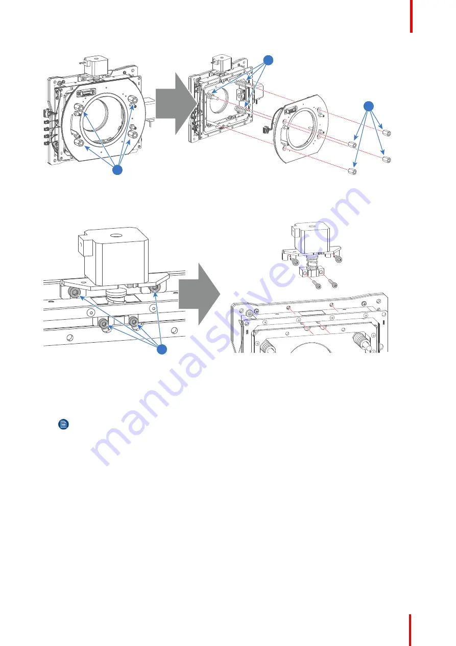
Remove the Vertical Shift stepper motor from the assembly by loosing the four screws (reference 5 Image 16-
28) 
as indicated. Use a 3mm and 4mm Allen wrench.

5

Image 16-28

3.

Remove the big bracket (reference 6 Image 16-29) and the small bracket (reference 8 Image 16-29) from the
old stepper motor and install these parts on the new stepper motor as illustrated. Use a T10 Torx driver for the
four screws (reference 7 Image 16-29) and a 10mm open end wrench for the small bracket (reference 9
Image 16-29).

Note:

The big bracket (reference 6 Image 16-29) used with the Vertical Shift stepper motor has two

cuts (reference 10 Image 16-29).

Lens Holder

Summary of Contents for DP2K SLP Series

Page 1: ...ENABLING BRIGHT OUTCOMES Service Manual DP2K SLP Series ...

Page 2: ...arco Visual Beijing Electronics Co Ltd 地址 北京市 昌平区 中关村科技园 昌平园 昌盛路 16号 www barco com en support www barco com Barco NV President Kennedypark 35 8500 Kortrijk Belgium www barco com en support www barco com ...

Page 3: ...ed in new editions of this publication The latest edition of Barco manuals can be downloaded from the Barco web site www barco com or from the secured Barco web site https www barco com en signin Copyright All rights reserved No part of this document may be copied reproduced or translated It shall not otherwise be recorded transmitted or stored in a retrieval system without the prior written conse...

Page 4: ......

Page 5: ...the ON OFF Switch 34 4 4 Replacing the Mains Filter 35 4 5 Replacing the Solid State relay 36 5 Switch Mode Power Supply SMPS 39 5 1 Introduction DP2K SLP Series SMPS board 40 5 2 Removing the SMPS board 40 5 3 Installing the SMPS board 42 5 4 Replacing the fans of the SMPS compartment 43 6 Laser Driver Module LDM 45 6 1 Removing the LDM 46 6 2 Installing the LDM 47 6 3 Replacing a driver board in...

Page 6: ...cessor 100 9 6 Cleaning the Prism exit side 103 9 7 Replacement of the fan of the Light Processor compartment 104 9 8 Replacement of the fan of the Red channel 107 9 9 Replacement of the fan of the Green channel 109 9 10 Replacement of the fan of the Blue channel 110 9 11 Authorization to clear security warning on the projector 112 10 Light Pipe 113 10 1 Introduction Light Pipe 114 10 2 Removal of...

Page 7: ...rtment 163 15 Color calibration Light measurements 165 15 1 Color calibration 166 15 1 1 Calibration process 166 15 1 2 White point calibration 166 15 1 3 Color gamut calibration 167 15 2 Light measurements for SmartCare contracts 169 15 2 1 Screen gain measuring 169 15 2 2 Measuring the light output 171 16 Lens Holder 173 16 1 Introduction Lens Holder 174 16 2 Available lenses 174 16 3 Lens selec...

Page 8: ...on of the Card Cage cover 245 18 23 Removal of the Card Cage partition plate 246 18 24 Replacement of the Status Light 247 19 Software update via Communicator DC update companion 249 19 1 Software upgrade launch DC update companion 250 19 2 Software upgrade projector ICMP or touch panel 252 19 3 ICP software upgrade 257 19 4 Link decryptor software update 259 19 5 Update logging 262 20 Exhaust sys...

Page 9: ...aning the exterior of the projector 292 25 Troubleshooting 293 25 1 LDM 295 25 2 Troubleshooting checklist Cinema Control Board CCB 296 25 3 Troubleshooting checklist Laser Control Board LCB 345 25 4 Log files 378 26 Projector cleaning 383 26 1 Necessary tools products and tips 384 26 2 General cleaning procedure for optical components 384 26 3 Cleaning process for the optical path 385 26 4 Cleani...

Page 10: ...R5906848 04 DP2K SLP Series 10 ...

Page 11: ...ons are given depending on the procedure Read and follow these warnings and cautions as well WARNING This manual is only intended for qualified service personnel Clarification of the term DP2K SLP Series used in this document When referring in this document to the term DP2K SLP Series means that the content is applicable for following Barco products DP2K 10SLP DP2K 8SLP Barco provides a guarantee ...

Page 12: ...ot limited to circuit modifications and the addition of items such as auxiliary audio and or video output connections might alter the safety characteristics of this apparatus and create a hazard to the user Any design alterations or additions may void the manufacturer s warranty and may make you the servicer responsible for personal injury or property damage resulting therefrom 4 Hot Chassis Warni...

Page 13: ...ipative surface such as a 3M No 8210 table mat to prevent electrostatic charge buildup or exposure of the assembly c Do not use freon propelled chemicals These can generate electrical charges sufficient to damage ES devices d Do not remove a replacement ES device from its protective package until immediately before you are ready to install it Most replacement ES devices are packaged with leads ele...

Page 14: ...R5906848 04 DP2K SLP Series 14 Safety ...

Page 15: ...el such as the location of the main components projector status spare parts list etc Overview Convention projector orientation Location of the main components of the projector Projector Status Spare parts for DP2K SLP Series Projector block diagrams R5906848 04 DP2K SLP Series General 2 ...

Page 16: ...he side at your left hand when standing behind the projector and looking at the projection screen in front of the projector B L R F T Image 2 1 T Top of the projector L Left side of the projector Light Processor side F Front of the projector R Right side of the projector Light Source side Input side B Back side of the projector General ...

Page 17: ...Rear cover 2 Rear Exhaust assembly 3 Top cover 4 Top cover plate Light Processor compartment 5 Side cover plate Light Processor compartment 6 Left side cover 7 ON OFF cover 8 Light Source cover 9 Card Cage cover 10 Small dust filter 11 Small dust filter cover plate 12 Large dust filter 13 Large dust filter cover plate 14 Front cover Lens Holder cover General ...

Page 18: ...M 4 Cover plate of Light Source compartment 5 Fan of Light Processor compartment 6 Light Processor 7 Lens Holder 8 Card Cage 9 Switch Mode Power Supply SMPS 10 Cover plate SMPS compartment 1 2 3 4 5 6 7 Image 2 4 1 Cathode Fan assembly 2 Projector Status Light 3 ON OFF switch 4 Solid State Relay 5 Mains Input Filter 6 3 slot terminal block 7 Cold Mirror Fan assembly General ...

Page 19: ...D 3 Fan Green DMD 4 Fan Blue DMD 5 Light Sensor Module CLO functionality 6 Light Pipe Corner Block contains Fold Mirror 7 Light Pipe contains Light Pipe Lenses and Rod assembly 5 4 3 1 2 Image 2 6 1 Anode Fan assembly 2 Fan ICP top 3 Fan ICP board 4 Fan Card Cage compartment 5 Fans SMPS compartment General ...

Page 20: ...enance action required Standby mode In Standby mode the light source of the projector is turned OFF but all the electronics of the projector remain fully operational The projector is ready to start up the light source and project the image The status light is not different between Standby mode and light source ON mode fully operational Sleep mode If the projector is in Sleep mode then the status l...

Page 21: ...s available 2 5 Projector block diagrams Signal Backplane diagram Switch 1 Switch 2 P Switch 4 Switch 3 J15 FANS LENSSIDE PUMP J17 LENS MOTORS J281 CATEYE J18 FANS LAMPSIDE PUMP J102 J103 J104 J105 J102 J103 J104 J105 B3244373 LPS RELAY 25A J799 J263 J11 AMB TEMP SENSOR In Harbin A series Not in Harbin A Mains Filter 25A B3058365 Projector ID J291 J292 J264 J19 J16 Pump J18 Projection Lens R768104...

Page 22: ...FIT 10 uFIT 10 uFIT 12 4 PH 4 J5 PH 5 J100 POWER 24V LSR DRV J500 uFIT 10 36V 2A9 J901 uFIT 4 SAFETY SWITCHES J501 J800 J401 J801 J802 J202 J600 FANS PUMP PA 4 ZH 2 PA 3 Molex Microclasp P30 XAD 8 LCB CONTROL J200 J800 Signal Backplane R7681040 R7860036 LCB CONTROL XAD 8 PH 2 COOLANT IN J403 J404 COOLANT OUT PH 2 PH 2 AIR OUT SPARE TEMP1 J405 J406 AIR IN SPARE TEMP2 PH 2 PH 8 J407 PELTIER INTERF 2...

Page 23: ...H 2 COOLANT OUT J404 J403 COOLANT IN PH 2 XAD 8 LCB CONTROL Signal Backplane R7681040 R7860036 J800 J200 LCB CONTROL XAD 8 Molex Microclasp P30 PA 3 ZH 2 PA 4 FANS PUMP J600 J202 J802 J801 J401 J800 J501 SAFETY SWITCHES uFIT 4 J901 36V 2A9 uFIT 10 J500 LSR DRV POWER 24V J100 PH 5 J5 PH 4 4 uFIT 12 uFIT 10 uFIT 10 uFIT 10 J123 PELTIER 3 PELTIER 2 J122 J121 PELTIER 1 J103 BLU LASERS 7 8 2xNTC BLU LA...

Page 24: ...R5906848 04 DP2K SLP Series 24 General ...

Page 25: ...tions not included in this manual which must be done by certified service personnel who are familiar with potential hazards of the product and all product safety checks Contact your service partner for more information about maintenance services Overview 1 month maintenance actions 3 month maintenance actions 1 year maintenance actions 4 year maintenance actions R5906848 04 DP2K SLP Series Prevent...

Page 26: ...he surface of the lens output side for dust it is not needed to remove the lens from the projector Only clean if necessary Clean the lens output side in case dust is clearly visible upon the surface Note if the lens was removed from the projector a manual Lens Home Return action must be executed to calibrate the position of the lens in relation to the Lens Holder This way the references of the exi...

Page 27: ...sm See service manual chapter Cleaning the Prism exit side page 103 Replace the complete Light Processor Unit in case of degradation cracks etc See service manual chapter Light Processor page 95 5 Dust in general Check the porthole both sides for dust Only clean the porthole in case dust is clearly visible upon the surface Use an optical cloth 6 Dust in general Clean the projector exterior housing...

Page 28: ...se an optical cloth See service manual chapter Cleaning the lens page 292 Note if the lens was removed from the projector a manual Lens Home Return action must be executed to calibrate the position of the lens in relation to the Lens Holder This way the references of the existing lens files remain valid See user guide of the Communicator software 17 Lens Check the lens Zoom Focus motors Use the lo...

Page 29: ...maintenance actions listed below may ONLY be performed by certified service personnel who are familiar with potential hazards of the product and all product safety checks No Maintenance action Remarks 1 Check all fans vibrations noise speed etc speeds via diagnostics Replace if needed Preventative maintenance actions ...

Page 30: ...R5906848 04 DP2K SLP Series 30 Preventative maintenance actions ...

Page 31: ...ral parts of the projector mains input Overview Introduction DP2K SLP Series Mains Input Accessing the Mains Input compartment Replacing the ON OFF Switch Replacing the Mains Filter Replacing the Solid State relay R5906848 04 DP2K SLP Series Mains Input 4 ...

Page 32: ... input filter and a solid state relay The Mains Input compartment is located at the rear right side of the projector The purpose of the solid state relay is to switch off the Light Source when the projector is in Sleep mode Component identification Mains Input 2 3 1 4 Image 4 1 1 ON OFF switch 2 Solid state relay 3 Mains filter 4 Terminal block Mains Input ...

Page 33: ...ower cord of the projector from the power net and wait a few minutes to discharge the capacitors prior to starting this procedure Required tools Flat screwdriver 8 mm How to access the compartment of the Mains Input 1 Remove the rear cover of the projector See procedure Removal of the rear cover page 272 2 Remove the cover of the Mains Input compartment by releasing the two captive thumb screws re...

Page 34: ...ment See procedure Accessing the Mains Input compartment page 33 3 Remove the ON OFF switch from the projector chassis by loosening the two screws with reference 1 as illustrated in Image 4 5 Use a 2 5mm Allen wrench 4 Disconnect the four electrical wires from the ON OFF switch Use a medium size flat screw driver 5 Connect the LOAD side reference 2 Image 4 5 of the new ON OFF switch with the two l...

Page 35: ...mpartment page 33 3 Remove the Mains Filter from the projector chassis by loosening the two nuts with reference 1 as illustrated in Image 4 6 Use a 3mm Allen wrench 4 Disconnect the six electrical wires from the Mains Filter Use a 8mm open end wrench 5 Connect the LINE side reference 2 Image 4 6 of the new Mains Filter with the two loose wires from the ON OFF switch Fasten the nuts with a torque o...

Page 36: ...tment and install the rear cover of the projector See procedure Accessing the Mains Input compartment page 33 4 5 Replacing the Solid State relay Required tools 3mm Allen wrench Medium size flat screw driver or Phillips PH2 screw driver Torque screw driver with PH2 socket How to replace the Solid State relay 1 Switch off the projector and disconnect the power cord of the projector from the power n...

Page 37: ...y a torque of 2 3Nm 1 70 lbf ft upon the large screws LOAD and a torque of 1 1Nm 0 81 lbf ft upon the small screws Connect the black wire from the LOAD side of the Mains Filter with pin 1 of the Solid State relay reference 1 Image 4 7 Connect the white wire LPS cable with pin 2 of the Solid State relay reference 2 Image 4 7 Connect the thin red wire with pin 3 of the Solid State relay reference 3 ...

Page 38: ...R5906848 04 DP2K SLP Series 38 Mains Input ...

Page 39: ... for the DP2K SLP Series projector More in detail is explained how to replace the SMPS Overview Introduction DP2K SLP Series SMPS board Removing the SMPS board Installing the SMPS board Replacing the fans of the SMPS compartment R5906848 04 DP2K SLP Series Switch Mode Power Supply SMPS 5 ...

Page 40: ...ins filter one to connect the PE wire one to connect the control signals and two for the DC output voltages connected with the Power Backplane Connections 1 2 3 4 5 Image 5 1 1 Mains Power 2 Protected Earth PE 3 Control signals 4 DC output voltages 2 large socket 5 DC output voltages 1 small socket 5 2 Removing the SMPS board WARNING Disconnect the power cord of the projector from the power net an...

Page 41: ...he following connectors Power out connector 2 reference 2 Image 5 3 Power out connector 1 reference 1 Image 5 3 Control connector reference 3 Image 5 3 Ground wire reference 4 Image 5 3 Mains input reference 5 Image 5 3 2 1 3 4 5 Image 5 3 3 Pull the SMPS board completely out of its compartment Image 5 4 Switch Mode Power Supply SMPS ...

Page 42: ... opening of the SMPS compartment Caution Ensure that the both sides of the SMPS board are captured by the guides inside the SMPS compartment See reference 1 of Image 5 5 1 Image 5 5 2 Make the electrical connections Power out connector 1 reference 1 Image 5 6 Power out connector 2 reference 2 Image 5 6 Control connector reference 3 Image 5 6 Ground wire reference 4 Image 5 6 Mains input reference ...

Page 43: ...MPS compartment behind the small dust filter of the projector To access the SMPS fans the projector small dust filter has to be removed This procedure assumes that the projector small dust files is already removed Required tools 2 5mm Allen wrench How to replace the fans of the SMPS compartment 1 Disconnect the wire of both SMPS fans reference 1 2 Image 5 8 1 2 Image 5 8 2 Remove the fans from the...

Page 44: ... fasten the screws reference 3 Image 5 9 of the fans Caution Ensure that the airflow of the fans is towards the SMPS compartment 4 Connect the wire of both fans with the projector The wire of the left fan with the left socket reference 1 Image 5 8 The wire of the right fan with the right socket reference 2 Image 5 8 Switch Mode Power Supply SMPS ...

Page 45: ...Functionality To power each Laser bank a Laser Driver Modules LDM has been provided to the projector The LDM is located at the rear end of the projector Overview Removing the LDM Installing the LDM Replacing a driver board in an LDM unit Removing a fan from an LDM Installing a new fan onto an LDM Replacing a Laser Drive Module R5906848 04 DP2K SLP Series Laser Driver Module LDM 6 ...

Page 46: ... remove the LDM from the projector 1 Remove the rear cover and left side cover from the projector 2 Disconnect the two MAINS INPUT wires reference 1 Image 6 1 and the PE wire reference 2 FROM the LDM 3 2 4 1 Image 6 1 3 Disconnect all other wire units from the LDM 4 Remove the fixation bracket as illustrated Use a flat screwdriver to loosen the captive screw reference 7 of the fixation bracket 7 I...

Page 47: ...ng the LDM Image 6 3 6 2 Installing the LDM How to install the LDM of the projector 1 Gently slide the LDM in its compartment as illustrated Image 6 4 2 Install the fixation bracket as illustrated Use a Flat screwdriver to fasten the captive screw reference 7 of the bracket Laser Driver Module LDM ...

Page 48: ...re unit with the LDM reference 4 6 Install the rear cover and left side cover of the projector 6 3 Replacing a driver board in an LDM unit CAUTION This procedure assumes the Laser Driver Module is removed from the projector chassis This procedure follows the example of one specific driver board This procedure is identical for every other driver board and power module in both LDM units Required too...

Page 49: ...move all screws washers and tabs holding the bottom plate to the module Use a 2 5 mm Allen wrench Image 6 7 Removing the screws washers and tabs from an LDM 3 Remove the bottom plate insulation and the fixation rails as illustrated Image 6 8 Removing the bottom plate and rails 4 Unplug and remove the desired driver board Laser Driver Module LDM ...

Page 50: ...stall a new driver board 1 If the old fuse has been removed replace it with a new one provided in the spare part kit of the driver board 2 Plug in the new laser driver board as illustrated Image 6 11 Example of mounting a driver board Caution Make sure the new Laser Driver Board is properly clicked in the board connection 3 Place both fixation rails back on top of the laser driver boards Laser Dri...

Page 51: ... the LDM Caution Make sure not to forget the two washers and rivet mounts on the outer side of the LDM Image 6 12 6 4 Removing a fan from an LDM Required tools 2 5 mm Allen wrench How to replace a fan from an LDM 1 Flip the Module upside down 2 Remove all screws washers and tabs holding the bottom plate to the module Use a 2 5 mm Allen wrench Image 6 13 3 Remove the bottom plate Laser Driver Modul...

Page 52: ...age 6 14 4 Remove the five screws holding the fan assembly onto the module Use a 2 5 mm Allen wrench Image 6 15 5 Unplug the fan cable of the desired fan 2 1 Image 6 16 1 Fan 1 2 Fan 2 6 Remove the fan assembly Laser Driver Module LDM ...

Page 53: ...ng a new fan onto an LDM CAUTION This procedure assumes that the fan assembly has been disassembled from the LDM Refer to Removing a fan from an LDM page 51 Required tools Allen wrench 2 5 mm How to install a new fan onto the LDM 1 Plug the new fan onto the snap rivets of the fan assembly as illustrated Laser Driver Module LDM ...

Page 54: ...e 6 19 2 Check if the mounting pin is set at its correct position A B Image 6 20 Mounting pin A Position for the Driver Module B Position for the Power Module 3 Place the fan assembly back into the LDM Image 6 21 Laser Driver Module LDM ...

Page 55: ...crews holding the fan assembly onto the module Use a 2 5 mm Allen wrench Tip There are three screws on the top plate and two screws on the back plate Image 6 23 6 Flip the module and place the bottom plate back in its place Image 6 24 7 Tighten all five screws back onto the top of the bottom plate Laser Driver Module LDM ...

Page 56: ...ge 6 25 6 6 Replacing a Laser Drive Module How to replace the module of the LDM 1 Remove all LDM boards from the old Laser Drive Module Refer to Replacing a driver board in an LDM unit page 48 2 Remove all screws washers and tabs holding the bottom plate to the module Use a 2 5 mm Allen wrench Image 6 26 3 Remove the bottom plate and the fixation rails as illustrated Laser Driver Module LDM ...

Page 57: ...Series 57 Image 6 27 4 Install all LDM boards into the new module Image 6 28 5 Place both fixation rails back on top of the Laser Driver Boards 6 Place the bottom plate back on the Module Image 6 29 Laser Driver Module LDM ...

Page 58: ... five screws back onto the top of the bottom plate 8 Tighten all three screws back on the front side of the Module Caution Make sure not to forget the two washers and rivet mounts on the outer side of the Module Image 6 30 Laser Driver Module LDM ...

Page 59: ...Optical alignment page 147 Overview Overview Removing the Light Source Removal of the Controller assembly Replacing the Laser Control Board LCB Replacing the Peltier Controller Replacing the 24V Filter board Mounting of the Controller assembly Installing the Light Source Replacing the Phosphor Wheel Interconnection Board Replacing the Phosphor Wheel Monitoring Interconnection Board Replacing the L...

Page 60: ...d 2 Controller Assembly 3 Cooling Liquid reservoir 4 Blue Laser Interconnection Board 5 6 9 10 7 8 Image 7 2 5 Fan assembly 6 Phosphor Wheel Monitoring Interconnection Board 7 Phosphor Wheel Interconnection Board 8 Light Sensor Interconnection Board 9 Combiner unit 10 Phosphor wheel Laser Phosphor Light Source ...

Page 61: ... reference 3 Image 7 3 and the data driver control cable reference 4 from the LDM 3 2 4 1 Image 7 3 3 Release the LCB Control cable connector reference 5 Image 7 4 located on the Phosphor wheel side of the Light Source 5 Image 7 4 4 Loosen the set screws holding the Light Source onto the projector frame reference 6 Image 7 5 Use a flat screwdriver to loosen the screws Laser Phosphor Light Source ...

Page 62: ... Image 7 6 7 3 Removal of the Controller assembly Required tools Allen wrench 3 mm Flat screwdriver 7 mm Side cutter How to remove the Controller assembly 1 Remove the Light Source Cover 2 Cut the cable ties holding the Light Source wiring to the Controller assembly Laser Phosphor Light Source ...

Page 63: ... and from both the Laser Control Board LCB and Peltier Controller 4 Loosen the 2 set screws holding the Controller assembly onto the light source but do not remove them reference 1 Image 7 8 1 Image 7 8 5 Remove the Controller assembly from the light source as illustrated Use a 3 mm Allen wrench to release the two hex screws reference 2 Image 7 9 Laser Phosphor Light Source ...

Page 64: ...tween the LCB and the Capacitor Board 3 Replace the LCB as illustrated Use a T10 Torx screwdriver to release the 6 Torx screws Image 7 10 4 Reconnect the wiring between LCB and Peltier Controller and between LCB and Capacitor Board 5 Mount the Controller assembly back onto the Light Source 7 5 Replacing the Peltier Controller How to replace the Peltier Controller 1 Remove the Controller assembly f...

Page 65: ... onto the Light Source 7 6 Replacing the 24V Filter board How to replace the 24V Filter board 1 Remove the Controller assembly from the projector See Removal of the Controller assembly page 62 2 Release the wire unit between the LCB and the Filter board 3 Replace the Filter board as illustrated Use a T10 Torx screwdriver to release the 2 Torx screws Image 7 12 4 Reconnect the wiring between LCB an...

Page 66: ...llen wrench to Tighten the two hex screws reference 2 Image 7 13 2 Image 7 13 2 Tighten the 2 set screws on the topside of the Controller assembly reference 1 Image 7 14 1 Image 7 14 3 Reconnect the wiring onto the Controller assembly 4 Place cable binders to hold the light source wiring onto the controller assembly Do this as illustrated reference 1 Image 7 15 Laser Phosphor Light Source ...

Page 67: ... with the same name 1 Image 7 16 2 Install the Controller assembly See Mounting of the Controller assembly page 66 3 Tie together the LDM driver cables and other data cables with the light source tubing Do this to make sure none of the cables get crushed or go missing when sliding in the light source Tip Use tie binders or tape that can be easily removed after the light source has been mounted Do ...

Page 68: ...ge 7 19 2 Guide the group of tubing and wiring through the other side of the projector After that do the following 1 Cut the tie or tape that binds the tubing and other wiring together 2 Carefully move the tubing to the left side of the Light source so that it s not touching either of the two mechanical brackets 3 Guide the Driver cables through the hole on the right to the LDM compartment Laser P...

Page 69: ...t screws holding the Light Source onto the projector frame reference 6 Image 7 21 Use a flat screwdriver 6 Image 7 21 4 Connect the LDM driver cables reference 3 Image 7 22 and the data driver control cable reference 4 from the LDM Laser Phosphor Light Source ...

Page 70: ...ource compartment instead of the LDM compartment 5 Image 7 23 6 Install the Right Side cover back cover and Light Source Cover 7 9 Replacing the Phosphor Wheel Interconnection Board Required tools Phillips screwdriver PH1 Side cutter Required parts Phosphor Wheel Interconnection Board Cable binders How to replace the Interconnection Board 1 Remove the Left side cover Laser Phosphor Light Source ...

Page 71: ...1 Image 7 24 3 Release the Phosphor Wheel Interconnection Board Cover Use a PH1 Phillips screwdriver to loosen the 4 screws Image 7 25 4 Disconnect all wiring from the Interconnection Board 5 Replace the Interconnection Board as illustrated Use a PH1 Phillips screwdriver to loosen and tighten the screws Image 7 26 Laser Phosphor Light Source ...

Page 72: ...ing the Light Source page 61 2 Remove the wire unit connected to the interconnection board 3 Spot and replace the light sensor Board as illustrated Use a PH1 Phillips screwdriver to loosen and tighten the 2 screws Image 7 27 4 Reconnect the wire unit to the Light Sensor Interconnection board 5 Install the light source back into the projector See Installing the Light Source page 67 7 11 Replacing t...

Page 73: ... as illustrated Use a 2 5 mm Allen wrench to loosen and tighten the screws Image 7 29 4 Reconnect all wire units to the Fan Interconnection board as illustrated Image 7 30 Caution Pay attention to the labels on the fan wires and the fan connector numbers Laser Phosphor Light Source ...

Page 74: ... the bottom of the Phosphor Wheel 3 Remove the protective cover over the interconnection board Use a 1 5 mm Allen wrench to remove the two screws 1 Image 7 31 4 Remove the wire unit connected to the interconnection board 5 Replace the light sensor Board as illustrated Use a PH1 Phillips screwdriver to loosen and tighten the screws Image 7 32 6 Reconnect the wire unit to the Light Sensor Interconne...

Page 75: ...screws Image 7 33 3 Remove the wire units connected to the interconnection board 4 Replace the Blue Laser Board as illustrated Use a PH1 Phillips scerwdriver to loosen and tighten the screws Image 7 34 5 Reconnect the wire unit to the Light Sensor Interconnection board 6 Place the protective cover back over the Blue Laser Interconnection Board Use a PH1 Phillips screwdriver to tighten the three sc...

Page 76: ... fan wire units connected to the interconnection board Image 7 35 3 Carefully cut the tie binders holding the fan cable tree to other wire units and tubing 4 Remove the Fan assembly from the Light Source assembly Use a 3 mm Allen wrench to loosen all six Allen screws Image 7 36 5 Spot and remove the desired fan from the assembly as illustrated Use a PH1 Phillips screwdriver to loosen tighten the 4...

Page 77: ...y direct them towards the Fan Interconnection board 9 Reconnect all wire units to the Fan Interconnection board as illustrated Image 7 38 Caution Pay attention to the labels on the fan wires and the fan connector numbers 10 Install the light source back into the projector See Installing the Light Source page 67 7 15 Replacing the combiner of the Light Source CAUTION This procedure assumes the ligh...

Page 78: ... Remove the wiring of the Light Sensor Interconnection board For more info see Replacing the Light Sensor Interconnection Board page 74 5 Remove the connectors of the two safety switches 6 Remove the screws holding the Combiner to the rest of the light source These are the following Four Torx screws holding the combiner to the phosphor wheel reference 3 Use a T20 Torx screwdriver to loosen these s...

Page 79: ... away the combiner from the rest of the light source Image 7 42 How to install the new combiner unit 1 Check the status of the O rings on the light source and the phosphor wheel 2 Remove the protective covers from the new combiner unit Laser Phosphor Light Source ...

Page 80: ... 7 44 4 Lock the combiner onto the light source Use the following screws Four Torx screws that will lock the combiner to the phosphor wheel reference 3 Use a T20 Torx screwdriver to tighten these screws Four hex screws that will lock the combiner to the rest of the light source unit reference 4 Use a 4 mm Allen wrench to tighten these screws Laser Phosphor Light Source ...

Page 81: ...e wiring to the safety switches 6 Reconnect the wiring back to the Light Source interconnection board For more info see Replacing the Light Sensor Interconnection Board page 74 7 Place the tubing into the protective holder of the combiner unit reference 2 Laser Phosphor Light Source ...

Page 82: ...oving the combiner unit Please first read and complete the combiner unit replacement procedure before attempting this procedure For more info see Replacing the combiner of the Light Source page 77 Required tools Allen wrench 4 mm Torx screwdriver T20 How to remove the phosphor wheel 1 Remove the combiner unit See Replacing the combiner of the Light Source page 77 2 Remove the four hex screws holdi...

Page 83: ...ge 7 48 3 Remove the old phosphor wheel as illustrated Image 7 49 4 Carefully remove the protective covers from the new phosphor wheel Use a T20 Torx screwdriver to loosen the screws of the protective covers Laser Phosphor Light Source ...

Page 84: ...e 77 7 17 Replacement of the Anode Fan To replace the Anode Fan the projector top cover and top cover plate must to be removed first This procedure assumes these covers are already removed Required tools 2 5mm Allen wrench 3mm Allen wrench How to replace the Anode Fan 1 Disconnect the wire of the Anode Fan reference 1 Image 7 51 and remove the wire from the wire clamp reference 2 Image 7 51 2 Remo...

Page 85: ...loosing the four screws reference 7 Image 7 53 as illustrated Use a 3mm Allen wrench 7 6 8 Image 7 53 7 Install a new Anode Fan onto the mounting plate Fasten the Anode Fan with four screws reference 7 Image 7 53 Use a 3mm Allen wrench Note Ensure that the wire of the Anode Fan is oriented as illustrated So it will match with the cut out in the cover reference 8 Image 7 53 8 Install the cover of t...

Page 86: ... 3 Image 7 51 which is attached to the Anode Fan assembly Note One flex cable is engaged into the cable clamp while the other is retained by the cable tie which should be located between knob and cable clamp 13 Install the top cover plate of the Light Processor compartment and the projector top cover 7 18 Replacement of the Cathode Fan To replace the Cathode Fan the Light Source has to be removed ...

Page 87: ...the four screws reference 4 Image 7 56 as illustrated Use a 2 5mm Allen wrench 5 Remove the mounting plate from the Cathode Fan by loosing the four screws reference 5 Image 7 56 as illustrated Use a 3mm Allen wrench 6 Install a new Cathode Fan on the mounting plate Fasten the Cathode Fan with four screws reference 5 Image 7 56 Use a 3mm Allen wrench Laser Phosphor Light Source ...

Page 88: ...Cathode Fan assembly are engaged in the foreseen slots in the projector chassis 10 Secure the Cathode Fan assembly with two screws reference 1 Image 7 54 Use a 3 mm Allen wrench 7 19 Replacement of the Cold Mirror fan To access the Cold Mirror fan assembly the projector left cover has to be removed This procedure assumes that the projector left cover is already removed Required tools 2 5mm Allen w...

Page 89: ...the wire through the two cable clamps Caution Ensure that the airflow of the fan is upwards oriented 3 Image 7 58 7 Place the Cold Mirror fan assembly halfway in its compartment 8 Connect the wire reference 2 Image 7 57 of the Cold Mirror fan 9 Insert the Cold Mirror fan assembly completely in its compartment 10 Fixate the Cold Mirror fan assembly with two screws reference 1 Image 7 57 Use a 2 5mm...

Page 90: ...R5906848 04 DP2K SLP Series 90 Laser Phosphor Light Source ...

Page 91: ...d inhalation of the noxious fumes WARNING Only use Barco approved cooling liquid to refill the liquid cooling circuit of the projector Neglecting this may lead to irreversible damage of the projector Handling the cooling liquid Avoid contact of the liquid with Eyes Skin and Clothing Avoid inhaling of the noxious fumes Conserve the product in the original package and in a well ventilated room Perso...

Page 92: ... dried cooling liquid turns into a crystallized white powder Since servicing of the light source cooling system is not supported if a leakage occurs the cooling pump is damaged or similar damage occurs to the cooling system the entire light source will need to be replaced How to check the liquid level 1 Remove the side cover on the light processor side Removal and installation of the projector cov...

Page 93: ...ot get damaged by removing the light source Take a look at the wiring on the backside of the light source while removing the light source If the wiring gets too tight remove the LDM wiring 4 Open filler cap by turning it anti clockwise Image 8 3 5 Place a clean funnel in the reservoir 6 Fill the reservoir with cooling liquid until the level is equal with the 600 indication on the reservoir 7 Remov...

Page 94: ...R5906848 04 DP2K SLP Series 94 10 Reinstall all covers Liquid cooling circuit ...

Page 95: ...st band which is connected to the ground while handling the electrostatic discharge sensitive parts CAUTION Remove the light processor of the projector only in a clean and dust free area Never remove the side cover in an area which is subject to airborne contaminants such as that produced by smoke machines or similar CAUTION Remove the projector lens before removing the Light Processor Overview In...

Page 96: ...essor for overheating Both the blue and the green channel DMD are equipped with three convergence adjustment knobs each The red channel DMD is fixed and serves as the reference channel for convergence alignment Two of the three adjustment knobs per channel red green are extended for easier access All critical air gabs are sealed The DMD are also sealed At the bottom of the prism exit a touch senso...

Page 97: ...UT SCC file into the projector file system e g 1110351581 LUT SCC See included procedure on page 155 Activate the LUT SCC file See included procedure on page 156 b If file does NOTexists activate the default LUT SCC file which is already installed on the ICP board For 2K projectors use the default LUT SCC file ones2K_LE For 4K projectors use the default LUT SCC file ones4K_LE 5 Backup projector fi...

Page 98: ...the Signal Distribution board Push the little tab reference 4 Image 9 4 down with your fingernail and then pull the connector gently out of its socket The connector should come out easily from its socket Caution Always push in the little tab of the connector to remove the connector from its socket Neglecting this will result in irreversible damage of the socket 4 3 Image 9 4 4 Disconnect the other...

Page 99: ...eel that the screws can bob up and down Use a 3mm Allen wrench Caution Do not keep turning the captive screws as this will dismantle the screws captive system 9 10 Image 9 6 6 Gently remove the Light Processor from the projector chassis Take the Light Processor by the black bracket reference 10 Image 9 6 which serves as a handle Image 9 7 Light Processor ...

Page 100: ... Notch Filter has to be replaced as well The Light Processor spare part kit contains a matched Notch filter for the Light Processor After installing a new Light Processor the LUT SCC file of the new Light Processor has to be installed and activated See chapter Spatial Color Calibration LUT SCC page 151 Required tools 7mm flat screwdriver 3mm Allen wrench How to install the Light Processor in the p...

Page 101: ...l Distribution board as illustrated Reference 1 small connector with blue cable tie Reference 2 small connector with green cable tie Reference 3 small connector with red cable tie Reference 4 connector with two blue cable tie Reference 5 connector with two green cable tie Reference 6 connector with two red cable tie Reference 7 connector with one blue cable tie Reference 8 connector with one green...

Page 102: ... Temperature Sensor DMD Green Channel orange wire with green cable tie Reference 8 Temperature Sensor DMD Red Channel orange wire with red cable tie 6 7 8 5 Image 9 12 5 Gently insert the Convergence flex cables into the corresponding cable clamp on the Anode Fan assembly and the cable clamp on the projector chassis reference 1 2 Image 9 13 1 2 Image 9 13 6 Place the top fan of the Light Processor...

Page 103: ...Calibration LUT SCC page 151 8 Close off the Light Processor compartment Install the top cover plate Install the side cover plate Install the top cover of the projector Install the left side cover of the projector 9 6 Cleaning the Prism exit side When should one clean the Prism exit side Clean the Prism exit on a regular basis to maintain light output level This procedure requires that the lens is...

Page 104: ... the fan of the Light Processor compartment To access the fan of the Light Processor compartment the top cover and the top cover plate have to be removed from the projector This procedure assumes that the top cover and top cover plate are already removed from the projector Required tools 3mm Allen wrench How to replace the fan of the Light Processor compartment 1 Disconnect the wire of the fan ref...

Page 105: ...m the cable clamp at the side reference 7 Image 9 16 5 6 7 Image 9 16 4 Remove the fan from the assembly Use a 3mm Allen wrench to release the four screws reference 3 Image 9 17 While remove the fan guide the wire through the grommet reference 4Image 9 17 Light Processor ...

Page 106: ...ference 2Image 9 17 Use a 3mm Allen wrench to fasten the four screws reference 3Image 9 17 Caution Ensure that the airflow of the fan is towards the Light Processor 6 Place the wire of the fan and the wire of the temperature sensor in the cable clamp reference 7 Image 9 16 7 Install the fan assembly Ensure that the four mounting pins reference 1 Image 9 18 of the fan assembly are engaged Light Pro...

Page 107: ... of the fan of the Red channel To access the fan of the Red channel in the Light Processor compartment the Light Processor unit has to be removed from the projector This procedure assumes that the Light Processor unit is already removed from the projector Required tools 3mm Allen wrench How to replace the fan of the Red channel 1 Disconnect the wire reference 3 Image 9 19 of the fan from the Signa...

Page 108: ...ly Use a 3mm Allen wrench to loosen the four screws reference 5 Image 9 21 as illustrated 6 5 8 7 9 Image 9 21 4 Mount the new fan on the assembly as illustrated Place the fan guard reference 6 Image 9 21 between the fan and mounting plate Fixate fan and fan guard with four long screws reference 5 Image 9 21 using a 3mm Allen wrench Caution Ensure that the airflow of the fan is towards the heatsin...

Page 109: ...reference 3 Image 9 19 9 9 Replacement of the fan of the Green channel To access the fan of the Green channel in the Light Processor compartment the Light Processor unit has to be removed from the projector This procedure assumes that the Light Processor unit is already removed from the projector Required tools 3mm Allen wrench How to replace the fan of the Green channel 1 Disconnect the wire refe...

Page 110: ...mage 9 24 and mark the wire by attaching a green colored cable tie two centimeters from the plug reference 9 Image 9 24 6 Install the fan assembly onto the projector chassis Use a 3mm Allen wrench to fasten the three screws reference 4 Image 9 23 7 Connect the wire of the fan with the Signal Backplane reference 2 Image 9 22 9 10 Replacement of the fan of the Blue channel To access the fan of the B...

Page 111: ...assembly Use a 3mm Allen wrench to loosen the four screws reference 5 Image 9 27 as illustrated 5 6 5 8 9 Image 9 27 4 Mount the new fan on the assembly as illustrated Place the fan guard reference 6 Image 9 27 on top of the fan and fixate fan and fan guard with four long screws reference 5 Image 9 27 using a 3mm Allen wrench Caution Ensure that the airflow of the fan is towards the heatsink of th...

Page 112: ...y warning Required tools Authorization pin code Authorization procedure to clear security warning 1 Ensure that all modules are properly installed 2 Start up the projector Standby mode 3 Initiate authorization by pushing the Key button on the Local Keypad The color of the backlight of the Numeric keys 1 to 6 of the Local Keypad changes from blue to yellow 4 Enter pin code within 5 seconds In case ...

Page 113: ...al of the Light Pipe cover plate Replacing Light Pipe lens No1 focus lens Replacing Light Pipe lens No2 Replacing Light Pipe lens No3 zoom lens Replacing Light Pipe lens No4 Cleaning the Light Pipe lenses Installing the Light Pipe cover plate Installing the Light Pipe Adjusting the Light Pipe lens No1 focus lens Adjusting the Light Pipe lens No3 zoom lens Replacing the Notch Filter Adjusting the N...

Page 114: ... up the light path of the projector to make the projector more compact the Light Pipe lens No4 and the Light Sensor Module which ensures a Constant Light Output CLO of the projector Note that the Light Processor and Lens Holder are directly mounted onto the Corner Block This ensures a precise mounting with minimum tolerance of all optical components in the light path which results in perfect optic...

Page 115: ...justment screw 11 High contrast plate 12 Light Pipe zoom adjustment screw 13 Fixation points for Lens Holder 10 2 Removal of the Light Pipe To remove the Light Pipe from the corner block the left side cover of the projector and the side cover plate of the Light Processor compartment has to be removed This procedure assumes that the cover and plate are already removed Required tools 3mm Allen wrenc...

Page 116: ...ht Pipe Use a 3mm Allen wrench 2 2 2 Image 10 4 3 Carefully move the Light Pipe one centimeter to the right and then move it gently away from the projector Place the Light Pipe on a clean surface Caution Do not bump accidentally with the lens reference 3 of the Light Pipe against the projector chassis Light Pipe ...

Page 117: ...omponents must be done in a dust free area While a strict cleanroom environment is not required do make sure dust is removed from the servicing area as much as possible Required tools 2 5mm Allen wrench How to remove the cover plate of the Light Pipe 1 Remove the 10 screws reference 1 Image 10 6 from the cover plate Use a 2 5mm Allen wrench 2 Remove the cover plate from the Light Pipe housing Ligh...

Page 118: ...ver plate page 117 2 Remove the adjustment screw reference 2 Image 10 7 of the Light Pipe focus lens Note that a spring and plain washer reference 3 4 Image 10 7 comes loose together with the adjustment screw Use a 5 5mm nut driver 3 Remove the lens container from the Light Pipe reference 5 Image 10 7 2 5 3 4 Image 10 7 4 Replace the focus lens reference 7 Image 10 7 from the container reference 8...

Page 119: ... See procedure Adjusting the Light Pipe lens No1 focus lens page 125 10 5 Replacing Light Pipe lens No2 To replace the Light Pipe lens No2 the Light Pipe has to be removed from the Corner Block This procedure assumes that the Light Pipe is already removed Required tools Cotton gloves never use gloves that leave particles on the surfaces How to replace the Light Pipe lens No2 1 Open the Light Pipe ...

Page 120: ...Cotton gloves never use gloves that leave particles on the surfaces 5 5mm nut driver 1 5mm Allen wrench How to replace the Light Pipe zoom lens 1 Open the Light Pipe housing See procedure Removal of the Light Pipe cover plate page 117 2 Remove the adjustment screw reference 5 Image 10 10 of the Light Pipe zoom lens Note that a spring and plain washer reference 4 3 Image 10 10 comes loose together ...

Page 121: ...towards Folding Mirror 6 Secure the lens container with the adjustment screw reference 5 Image 10 10 Place a spring and a plain washer reference 4 3 Image 10 10 on the adjustment screw Use a 5 5mm nut driver 7 Close the Light Pipe housing See procedure Installing the Light Pipe cover plate page 123 The Light Pipe zoom lens needs readjustment after replacement See procedure Adjusting the Light Pipe...

Page 122: ...ton gloves Do not touch the glass with bare hands Furthermore ensure that the lens remains clean Note Light Pipe lens No3 zoom lens and lens No4 are the biggest Light Pipe lenses Lens No3 and Lens No4 have a diameter of 60mm But lens No3 has an edge thickness of 7mm while lens No4 has an edge thickness of 5mm 5 Place the lens container back in the Corner Block as illustrated in Image 10 12 6 Faste...

Page 123: ...er with a clean lens cleaning cloth to remove the dust and contamination Use big wipes 3 Use a dry lens cleaning cloth to remove left liquid or stripes Polish with small circles 4 If there are still fingerprints on the surface wipe them off with lens cleaner together with a clean lens cleaning cloth Polish again with a dry one 10 9 Installing the Light Pipe cover plate Required tools 2 5mm Allen w...

Page 124: ...he Light Pipe in the corner block Caution Do not bump accidentally with the lens reference 3 Image 10 15 of the Light Pipe against the projector chassis 3 Image 10 15 2 Fixate the Light Pipe with five screws reference 2 Image 10 16 Use a 3mm Allen wrench 2 2 2 Image 10 16 3 Connect the wire reference 1 Image 10 17 of the temperature sensor Light Pipe ...

Page 125: ...full white internal pattern with a maximum contrast and a maximum dimming without activating the light source Make sure that you have a 5 5 mm nut driver within reach for the next steps 4 Activate the light source and zoom the projector lens in or out until the projected image is focused Note Dialog windows must be displayed sharp instead of blurry This is independent of the focus of the light bea...

Page 126: ...cover plate of the Light Processor compartment have to be removed Required tools Nut driver 5 5 mm How to adjust the Light Pipe zoom lens 1 Loosen the adjustment screw of the Light Pipe zoom lens reference 5 Image 10 18 a few turns Use a 5 5 mm nut driver Do not remove the adjustment screw 2 Start up the projector but do not activate the light source yet Caution Projecting a light spot which is la...

Page 127: ...eplacing the Light Processor the Notch Filter needs to be replaced as well The Light Processor spare part kit contains the matched Notch filter To access the old Notch Filter installed inside the projector the left side cover and side cover plate has to be removed from the projector This procedure assumes that the left side cover and side cover plate are already removed from the projector Matching...

Page 128: ... of the Light Processor 3 Fasten the Notch Filter with two hexagon head cap screws reference 1 Image 10 20 Use for that a 2 5mm Allen wrench 4 Readjust the Notch Filter See procedure Adjusting the Notch Filter page 128 10 14 Adjusting the Notch Filter Purpose of the Notch Filter The Notch Filter is a coated glass plate located in the middle of the Light Pipe assembly The Notch Filter applies some ...

Page 129: ...0 02 0 8 To access the Notch Filter the left side cover and the side cover plate have to be removed from the projector This procedure assumes that the left side cover and side cover plate are already removed from the projector Required tools 2 5mm Allen wrench Colorimeter e g CS 200 chroma meter from Konica Minolta or the PR 650 SpectraScan from Photo Research How to adjust the Notch Filter 1 Rele...

Page 130: ...he position of the Notch Filter Use for that a 2 5mm Allen wrench Make sure that the position of the Notch Filter remains unchanged while fastening the screw 10 15 Cleaning the Notch Filter When should one clean the Notch Filter Only clean the Notch Filter in case it is really necessary This means in case dust is clearly visible upon the surface of the Notch Filter This procedure requires removal ...

Page 131: ...Sensor module 1 Image 10 23 Type A Light Sensor 1 Image 10 24 Type B Light Sensor 2 Remove the side cover plate from the Corner Block Use a 2 5mm Allen wrench to loosen the three screws reference 1 Image 10 25 1 1 Image 10 25 3 Carefully remove the Light Sensor assembly from the Corner Block Use a 2 5mm Allen wrench to loosen the four screws reference 2 Image 10 26 Caution The adjustable Fold Mirr...

Page 132: ...uch the surface of the Fold Mirror Use cotton gloves to handle the Fold Mirror Ensure that the Fold Mirror remains clean 3 3 4 4 Image 10 27 5 Replace the adjustable Fold Mirror at the bottom of the Light Sensor assembly as illutrated Use a 5 5mm nut driver to loosen the three adjustment nuts reference 5 Image 10 28 Reuse the three springs reference 7 Image 10 28 and the three plain washers refere...

Page 133: ... via the Integration Rod upon the prism of the Light Processor The position of the light spot upon the DMD s can be adjusted with the Fold Mirror CAUTION Normally the Fold Mirror should never be readjusted in the field In case a readjustment is required follow the instructions in this chapter precisely Only qualified technicians who have experience with adjusting the Fold Mirror may adjust the Fol...

Page 134: ...to achieve a higher contrast of the projected image Then readjust the adjustment screws individual until the light spot matches with the outline of the DMDs Take into account that a higher contrast is at the expense of brightness 10 18 Cleaning the Fold Mirrors When should one clean the Fold Mirror Only clean the Fold Mirror in case it is really necessary This means in case dust is clearly visible...

Page 135: ...ntrast plate reference 1 Image 10 30 Use a 2 5mm Allen wrench 2 Remove the High Contrast plate and insert the new one 3 Fasten the High Contrast plate with two screws reference 1 Image 10 30 Use a 2 5mm Allen wrench 1 1 Image 10 30 10 20 Replacing the Light Sensor module CLO WARNING Disconnect the power cord from the projector and wait a few minutes to discharge the capacitors prior to start with ...

Page 136: ...here must be a plastic spacer reference 3 Image 10 33 between the Light Sensor board and chassis Normally the plastic spacers remained seated on the threaded rods when the Light Sensor board was removed 4 Connect the wire unit of the Light Sensor module 5 Install the side plate of the Light Processor compartment and the left side projector cover 6 Connect the power cord and switch on the projector...

Page 137: ...an reference 3 Image 10 35 3 Install the new fan as illustrated Place a fan guard reference 4 Image 10 35 at both sides of the fan reference 5 Image 10 35 Fixate fan and fan guards with four long screws reference 3 Image 10 35 using a 3mm Allen wrench Caution Ensure that the airflow of the fan is towards the Light Pipe 3 3 4 5 4 Image 10 35 4 Connect the wire of the fan reference 1 Image 10 34 5 G...

Page 138: ...R5906848 04 DP2K SLP Series 138 Light Pipe ...

Page 139: ...w to replace the Integration Rod and how to adjust the Integration Rod Overview Introduction of the Integration Rod Integration Rod diagnostic Removal of the Mask plate and Rod heatsink Replacing the Integration Rod Installing the Mask plate and Rod heatsink Adjusting the Integration Rod R5906848 04 DP2K SLP Series Integration Rod 11 ...

Page 140: ... never be contaminated with grease dirt liquid or the such For optimal protection the rod is mounted on an aluminium rod holder which requires replacing together with the rod The Integration Rod and the aluminium rod holder together form the Integration Rod assembly Parts Integration Rod assembly 2 1 Image 11 2 1 Integration Rod housing 2 Integration Rod entrance side CAUTION Never touch the entra...

Page 141: ...n Rod Otherwise the DMD s may be damaged 1 Image 11 3 5 Do you see spots in the projected image rotate along with the movements of the Integration Rod If yes these spots are caused by damages to the Integration Rod Replace the Integration Rod assembly If no Integration Rod is OK Re adjust and secure the Integration Rod and reinstall the side cover plate and projector cover 11 3 Removal of the Mask...

Page 142: ...es the Rod 4 Remove the Rod heatsink reference 7 Image 11 4 Note The temperature sensor mounted on the Rod heatsink has to be reused when installing the 3D color wheel Use a 2 5mm Allen wrench to remove the temperature sensor from the Rod heatsink 4 6 5 7 8 Image 11 4 11 4 Replacing the Integration Rod To replace the Integration Rod the Light Pipe has to be removed from the Corner Block This proce...

Page 143: ...he three holes in the Light Pipe housing to insert the screws Caution Wear cotton gloves and do not touch the glass of the Integration Rod Furthermore ensure that nothing hits accidentally the glass of the Integration Rod Note The spare part Integration Rod assembly comes with a protective cap mounted on the Rod entrance side reference 9 Image 11 6 This protective cap remains until the Integration...

Page 144: ...e entrance 1 Install the Rod heatsink as illustrated reference 7 Image 11 7 Fasten the Rod heatsink with two Torx countersunk head screws reference 6 Image 11 7 Use a TX10 Torx driver Note The Rod heatsink is provided with a temperature sensor reference 1 This temperature sensor must facing the Light Pipe as illustrated in Image 11 8 Caution Ensure that the Rod heatsink does NOT touches the Rod Ca...

Page 145: ...ved Required tools 5 5mm nut driver How to adjust the Integration Rod of the projector 1 Loosen the adjustment screw reference 1 Image 11 9 a few turns Use a 5 5 mm nut driver Do not remove the adjustment screw 2 Start up the projector but do not activate the light source yet 3 Set up the projector to display a full white internal pattern with a maximum contrast and a maximum dimming Do not activa...

Page 146: ...he adjustment screw This allows a more precise adjustment Warning The adjustment screw of the Integration Rod is hot To prevent burn injuries use 5 5mm nut driver for moving the Integration Rod Note No spots in the projected image may move along with the movements of the Integration Rod Spots which move with the movements of the Integration Rod indicates that the exit side of the Integration Rod i...

Page 147: ...147 R5906848 04 DP2K SLP Series Optical alignment 12 ...

Page 148: ...or more info refer to the user manual for Communicator 2 Set up the projector to display a full white pattern 3 Use the photometer to measure the current light output 4 Loosen the four fixation screws and remove the two cover plates reference 1 1 1 Image 12 1 Image 12 2 5 Loosen the two wing nuts reference 2 but do not remove them 2 Image 12 3 6 Manipulate the phosphor wheel to maximize the light ...

Page 149: ...have an impact on the light output Keep an eye on the photometer to spot the point where the light output is the highest Ignore the direction arrows underneath each screw These arrows only reflect internal mechanics and do not reflect the impact on the projected image Optical alignment ...

Page 150: ...R5906848 04 DP2K SLP Series 150 Optical alignment ...

Page 151: ...ced the Light Processor or ICMP ICP board Overview Introduction to SCC file Obtain the Serial Number of the installed Light Processor Download the LUT SCC file from the Barco website Upload Spatial Color Calibration file Activate Spatial Color Calibration file R5906848 04 DP2K SLP Series Spatial Color Calibration LUT SCC 13 ...

Page 152: ... software How to obtain the Serial Number of the installed Light Processor remotely 1 Start up the Communicator software version 4 7 9 2 or later Note The DP2K DP4K software package version 1 11 3 or later must be installed to read out the Light Processor serial via the Communicator 2 Create a Diagnostic Package of the projector For detailed instructions see User Guide of the Communicator chapter ...

Page 153: ...co website A logon ID is required to access the secured zone myBarco on the Barco website https www barco com A logon ID for the secured zone can be requested at the portal page of the Barco website Required parts Serial Number of the installed Light Processor How to download the Spatial Color Calibration file LUT SCC from the secured Barco website 1 Open the url https www barco com in a web brows...

Page 154: ...rch file button Image 13 4 If a LUT SCC files is found a download link will appear Proceed with the next step In case no LUT SCC file is found end this procedure and use the default LUT SCC file which is already installed on the ICP board For 2K projectors this is ones2K_LE for 4K projectors this is ones4K_LE 6 Click on the download link to download the LUT SCC file Image 13 5 Spatial Color Calibr...

Page 155: ...or LUT SCC file available on the PC of the Communicator or on USB stick when using the Communicator Touch Panel How to upload the LUT SCC file into the projector 1 Start up the projector and the Communicator version 4 7 9 4 or later 2 Ensure that the projector is connected with the Communicator Either via a direct connection or via network For detailed instructions see User Guide of the Communicat...

Page 156: ...e drop down box 1 next to Look in and select LUT SCC files 2 Image 13 7 Activate LUT SCC file 2 Select the desired file 4 3 Click Select active 5 In case no Light Processor serial LUT SCC file is available use the default LUT SCC file which is factory installed on the ICP board and thus displayed in the list For 2K projectors this is ones2K_ LE for 4K projectors this is ones4K_LE Spatial Color Cal...

Page 157: ... adjustment and how to adjust the convergence Overview Convergence controls Preparing for convergence adjustment Converging the blue pattern onto the red pattern Converging the green pattern onto the red pattern Closing off the Light Processor compartment R5906848 04 DP2K SLP Series Convergence 14 ...

Page 158: ... 1 The adjustment knobs are numbered from 1 to 6 and have the same color as the channel which they affect To access the control knobs the top cover and left side cover of the projector and the top cover plate and side cover plate of the Light Processor compartment have to be removed For easy access to control knobs No1 and No4 we advise locating the Light Processor top fan unit in it s upper posit...

Page 159: ...ssly abnormal and likely indicates abuse or rough handling However in extreme cases correction of up to 10 pixels is possible CAUTION The system does have an end of travel in either direction but using excessive force may cause damage Please handle gently Troubleshooting dead zone of control knob In the rare event that a knob is loose in the perfect convergence position it is preferable to continu...

Page 160: ...f the Light Processor in the upper position as illustrated Do this by engaging the two lower slots reference 2 Image 14 3 into the upper mounting pins as illustrated The two upper slots reference 3 Image 14 3 remain free 3 2 Image 14 3 6 Switch on the projector activate the light source and open the dowser 7 Select the convergence test pattern which is illustrated below Image 14 4 Use the communic...

Page 161: ...n the center of the projected image converges with the red pattern Note that a turn of a few degrees corresponds with one full pixel The direction on the control knob corresponds to the direction of the arrow of the test pattern 1 Image 14 5 2 Slightly turn the blue colored control knob number 2 until the blue pattern in the lower left of the projected image converges with the red pattern 2 5 Imag...

Page 162: ...tment procedure assumes that the projector is prepared for convergence adjustment Required tools No tools required How to converge the green pattern onto the red pattern 1 Slightly turn the green colored control knob number 4 until the green pattern in the center of the projected image converges with the red pattern Note that a turn of a few degrees corresponds with one full pixel The direction on...

Page 163: ...l coincidence is obtained of the green pattern in the center lower left and upper right of the projected image 6 Switch off the projector 7 Continue with the procedure Closing off the Light Processor compartment 14 5 Closing off the Light Processor compartment Required tools 7mm flat screwdriver 3mm Allen wrench How to close off the Light Processor compartment 1 Place the fan on top of the Light P...

Page 164: ...of the Light Processor compartment 3 Install the side cover plate of the Light Processor compartment 4 Install the top cover of the projector 5 Install the left side cover of the projector 6 Switch on the projector 7 Clear the security warning See procedure page 112 Convergence ...

Page 165: ...165 Overview Color calibration Light measurements for SmartCare contracts R5906848 04 DP2K SLP Series Color calibration Light measurements 15 ...

Page 166: ...lect target colors The target colors are stored in the Target Color Gamut Data TCGD file Several TCGD files are already available in the file system of the projector 6 For more info about color gamut calibration see Color gamut calibration page 167 The Communicator software contains a wizard for color gamut calibration See user guide of the Communicator for detailed menu navigation instructions 7 ...

Page 167: ...that horizontal and vertical directions describe saturation and luminance changes respectively When a color is out of gamut it is not possible to reach that color by the device 520 560 540 580 600 620 700 500 490 480 470 460 380 x y 0 9 0 8 0 7 0 6 0 5 0 4 0 3 0 2 0 1 0 0 0 0 0 1 0 2 0 3 0 4 0 5 0 6 0 7 0 8 1 Image 15 1 Sample Chromaticity Diagram with Color Gamut of target device 1 Why apply colo...

Page 168: ...tart with color gamut calibration ensure that the white point calibration is finalized successfully See White point calibration page 166 Color gamut calibration procedure 1 Check if the white point calibration is done If not see White point calibration page 166 2 Setup the ambient light conditions as it should be during the play out of the movie e g only the stairs and emergency exit lighting is s...

Page 169: ...ht under angles The resulting screen brightness in the perpendicular direction is Lb Screen gain is defined as the ratio of the reflected luminance produced by a projector beam of white light falling onto the screen surface compared with the reflected luminance of a reference standard with gain of 1 0 The screen gain of the second screen is Lb La Image 15 3 reference C illustrates the case when th...

Page 170: ...sure the luminance at the vertical center line of the screen 1 2 3 2 1 4 A B Image 15 5 2 Place the light meter 2 mounted on a tripod low and close to the screen in front of the vertical line at a height of around the screen bottom picture line 3 Adjust the vertical angle of the light meter until a peak luminance reading 3 L1 is measured from the screen orient the light meter visually towards the ...

Page 171: ...3D 5 Switch on the uncorrected white test pattern RGB 12bit FullScreenWhite uncorrected and let the projector warm up for at least 5 minutes in Communicator select Control Test Patterns Change pattern and select the correct pattern 6 During this time look for a reference measurement position in the center of the auditorium typically in the half or upper half of the seating area Place the light met...

Page 172: ...o one for 2D mode except the following points The projector must be set in 3D mode in Communicator select Configuration 3D Activate 3D file and select the corresponding 3D file for your 3D system All measurements must be done with a light meter looking through a 3D glass towards the screen Color calibration Light measurements ...

Page 173: ...n damage the Lens Holder and Prism CAUTION Caution when removing or installing the lens Fragile parts at the inner side of the Lens Holder Each time a lens is manipulated e g removed and installed in a projector it needs to be homed and returned Overview Introduction Lens Holder Available lenses Lens selection Lens installation Lens removal Lens shift zoom focus Removal of the Lens Holder cover pl...

Page 174: ...7 8 10 11 9 12 Image 16 1 1 Electrical socket lens connection 2 Wire lens connection zoom focus orange wires 3 Horizontal Left end loop wires yellow black 4 Vertical Top end loop wires red black 5 Vertical Bottom end loop wires brown black 6 Horizontal Right end loop wires orange black 7 Lens lock handle 8 Lens Holder front plate 9 Lens Holder Vertical Shift motor 10 Lens Holder Horizontal Shift m...

Page 175: ...oom lens 2 3 9 R9856524 16 3 Lens selection Which lens do I need 1 Go to Barco s website on www barco com and click on myBarco 2 Login on If you are not yet registered create a login and password With the created login and password it is possible to enter myBarco When your login is correct the start page is displayed 3 Click the Support tab then Digital cinema calculator on the left of the screen ...

Page 176: ... use the lens at one of its extreme zoom positions this should be taken into account 16 4 Lens installation How to install a lens into the Lens Holder 1 Remove the foam rubber in the opening of the Lens Holder if not removed yet 2 Take the lens assembly out of its packing material and remove the lens caps on both sides Caution Do not touch the glass of the lens 3 Ensure that the Lens Holder stands...

Page 177: ... and removal of the lens it is recommended to install the lens while the lock handle is in open position upwards and put the lock handle in locked position once the lens is inserted Then check if the lens is properly installed by trying to pull the lens out of the Lens Holder this alternative procedure result in less wear of the Lens Holder 7 Check if the lens is really secured by trying to pull t...

Page 178: ...into the Lens opening to prevent intrusion of dust Note that this foam rubber is packed in a plastic bag to prevent the dust emitted by the foam from entering the projector 16 6 Lens shift zoom focus Motorized lens adjustment The DP2K SLP Series is equipped with a motorized lens shift and zoom focus functionality Maximum shift range The lens can be shifted with respect to the internal optics of th...

Page 179: ...left and right arrow buttons on the Local Keypad to shift the lens horizontally SHIFT Image 16 12 How to zoom in or out 1 Use the and zoom buttons on the Local Keypad to zoom in or out ZOOM Image 16 13 How to focus 1 Use the and focus buttons on the Local Keypad to focus the image on the screen FOCUS Image 16 14 Take into account that the lens focus may slightly drift while the lens is warming up ...

Page 180: ...component is already removed Required tools Phillips screwdriver PH2 How to remove the cover plate of the Lens Holder 1 Remove the lens from the projector See chapter Lens removal page 178 2 Remove the large dust filter from the projector See chapter Check the large dust filter page 284 3 Remove the rubber dust ring from the Lens Holder front plate Image 16 15 4 Remove the screw reference 1 Image ...

Page 181: ...te of the Lens Holder have to be removed This procedure assumes that these components are already removed Required tools 5mm Allen wrench 5 5mm nut driver How to remove the Lens Holder from the projector 1 Disconnect the wire unit reference 3 Image 16 17 of the vertical shift motor and the wire unit reference 4 Image 16 17 of the horizontal shift motor 3 4 Image 16 17 2 Disconnect the 5 wires refe...

Page 182: ...age 16 19 from the projector chassis Use a 5 5mm nut driver 10 Image 16 19 4 Remove the Lens Holder from the projector chassis by loosening the 4 screws reference 1 Image 16 20 as illustrated Use a 5mm Allen wrench Note that each screws contains a plain washer reference 2 Image 16 20 Lens Holder ...

Page 183: ...ools 5mm Allen wrench 5 5mm nut driver How to install the Lens Holder 1 Place the Lens Holder on the projector chassis as illustrated and fasten with the 4 screws reference 1 Image 16 21 Use a 5mm Allen wrench Ensure to place a plain washer onto each screws reference 2 Image 16 21 Lens Holder ...

Page 184: ...nect the 5 wires at the left side from the Lens Holder as illustrated reference 5 in Image 16 23 Lens wires zoom focus orange wires reference 6 in Image 16 23 Horizontal Left end loop wires yellow black reference 7 in Image 16 23 Vertical Top end loop wires red black reference 8 in Image 16 23 Vertical Bottom end loop wires brown black reference 9 in Image 16 23 Horizontal Right end loop wires ora...

Page 185: ... See Scheimpflug page 199 16 10 Installation of the Lens Holder cover plate Required tools Phillips screwdriver PH2 How to install the cover plate of the Lens Holder 1 Place the cover plate of the Lens Holder in its place 2 Fasten the cover plate with three screws reference 2 Image 16 25 Use a Phillips screwdriver PH2 3 Insert the screw reference 1 Image 16 25 at the lower left side of the cover p...

Page 186: ...mm Allen wrench T10 Torx driver 13mm nut driver 10mm open end wrench How to replace the Vertical Shift stepper motor of the Lens Holder 1 Remove the front plate from the Lens Holder Use a 13mm nut driver to loosen the four Scheimpflug nuts reference 3 Image 16 27 as illustrated It s not necessary to disconnect the ground wire from the front plate Just turn the front plate away for accessing the st...

Page 187: ...ket reference 6 Image 16 29 and the small bracket reference 8 Image 16 29 from the old stepper motor and install these parts on the new stepper motor as illustrated Use a T10 Torx driver for the four screws reference 7 Image 16 29 and a 10mm open end wrench for the small bracket reference 9 Image 16 29 Note The big bracket reference 6 Image 16 29 used with the Vertical Shift stepper motor has two ...

Page 188: ...er has to be adjusted after installation See chapter Scheimpflug page 199 16 12 Replacement of the Horizontal Shift stepper motor This procedure assumes that the Lens Holder is removed from the projector See Removal of the Lens Holder page 181 Required tools 4mm Allen wrench 3mm Allen wrench T10 Torx driver 13mm nut driver 10mm open end wrench How to replace the Horizontal Shift stepper motor of t...

Page 189: ...cket reference 6 Image 16 32 and the small bracket reference 8 Image 16 32 from the old stepper motor and install these parts on the new stepper motor as illustrated Use a T10 Torx driver for the four screws reference 7 Image 16 32 and a 10mm open end wrench for the small bracket reference 9 Image 16 32 Note The big bracket reference 6 Image 16 32 used with the Horizontal Shift stepper motor has o...

Page 190: ...tion of the Lens Holder cover plate page 185 The Lens Holder has to be adjusted after installation See chapter Scheimpflug page 199 16 13 Replacement of the motor assembly for 0 69 DC2K lenses Type M To know which type of lens motor assembly is mounted on the projection lens see chapter Available lenses page 174 Required tools 2 5mm Allen wrench with ball end Adhesive anti loosening agent for hex ...

Page 191: ...crews M3x8 reference 2 Image 16 34 Use a 2 5mm Allen wrench with ball end Image 16 35 5 Adjust the meshes between motor gear and lens gear to ensure that the Motor Unit will drive properly Note DO NOTset the lens gears at the terminal position Focus and Zoom lens gears respectively Tip Because of limited accessibility it is recommendable to use the 2 5mm Allen wrench with ball end Ball end for fas...

Page 192: ... 36 16 14 Replacement of the motor assembly for 0 69 DC2K lenses Type F To know which type of lens motor assembly is mounted on the projection lens see chapter Available lenses page 174 How to replace the lens motor assembly 1 Remove the lens from the projector 2 Remove the front cover reference 2 Image 16 37 of the lens motor assembly by releasing the three screws reference 1 Image 16 37 as illus...

Page 193: ... See Image 16 38 8 Install the top cover and front cover of the lens motor assembly See Image 16 37 16 15 Replacement of the motor assembly for 0 69 DC2K lenses Type B To know which type of lens motor assembly is mounted on the projection lens see chapter Available lenses page 174 How to replace the lens motor assembly 1 Remove the lens from the projector 2 Place the lens in vertical position as i...

Page 194: ... 16 41 2 Image 16 41 4 Inverse the lens position and remove the motor block from the lens chassis Use an Allen wrench to loosen the two screws reference 3 Image 16 42 of the motor block 3 3 Image 16 42 5 Place the new motor block into position and secure with two screws reference 3 Use an Allen wrench to fasten the two screws reference 1 Image 16 42 Lens Holder ...

Page 195: ...erence 1 Image 16 40 16 16 Replacement of the Inner Dust Rubber This procedure assumes that the Lens Holder is removed from the projector See procedure Removal of the Lens Holder page 181 CAUTION Be careful as not to damage the inner dust rubber while executing this procedure Required tools 13 mm nut driver or open end wrench 5 5 mm nut driver or box end wrench PH1 Phillips screwdriver Required pa...

Page 196: ...pflug adjustment mechanism reference 4 3 4 Image 16 45 2 Remove the old Lens Holder cover and inner dust rubber Use a PH1 Phillips screwdriver to loosen the seven screws reference 5 Image 16 46 as illustrated by doing this you will also release the ground cable reference 6 5 6 Image 16 46 3 Place the inner dust rubber reference 9 Image 16 47 over the pins of the new cover Carefully place the dust ...

Page 197: ...all the front plate from the Lens Holder Help the rubber through the lens Holder onto the other side Image 16 48 6 Carefully reinstall the front plate from the Lens Holder Use a 13 mm nut driver to fasten the four Scheimpflug nuts reference 3 Image 16 45 Fasten the big nuts crosswise bit by bit Ensure that the upper two rods and the lower left rod contain a big spring reference 4 Proceed with rein...

Page 198: ...R5906848 04 DP2K SLP Series 198 The Lens Holder has to be adjusted after installation See chapter Scheimpflug page 199 Lens Holder ...

Page 199: ...focus When the DMD plane and lens plane are parallel the plane of sharp focus will also be parallel to these two planes If however the lens plane is tilted with respect to the DMD plane the plane of sharp focus will also be tilted according to geometrical and optical properties The DMD plane the principal lens plane and the sharp focus plane will intersect in a line below the projector for downwar...

Page 200: ...an be achieved by turning the lens holder to remove the tilt or swing between lens plane and DMD plane Lp3 Lp4 Image 17 1 Scheimpflug principle Scheimpflug principle The plane of sharp focus can be changed so that any plane can be brought into sharp focus When the DMD plane and lens plane are parallel the plane of sharp focus will also be parallel to these two planes If however the lens plane is t...

Page 201: ...T in parallel with the screen or a previous misaligned Scheimpflug Take into account that the consequence of applying Scheimpflug correction upon a screen not in parallel with the projector is that the projected image differs from the rectangle shaped image In other words distortion of the projected image occurs Masking will be required to solve the distortion The disadvantage of Masking is loss o...

Page 202: ...cted image If yes the Back Focal Length is OK Proceed with the next step If no the Back Focal Length needs realignment Proceed with the procedure Back Focal Length adjustment page 205 7 Unlock and turn out the 4 set screws reference 11 Image 17 4 of the Lens Holder by 1 centimeter Use a 10mm nut driver for the lock nuts reference 21 Image 17 4 and use a 3mm Allen wrench for the set screws 11 11 21...

Page 203: ... screen by turning the lower right Scheimpflug adjustment nut reference 3 Image 17 7 F 3 Image 17 7 3 Sharpen the image at the bottom right corner of the screen by turning the upper right Scheimpflug adjustment nut reference 2 Image 17 7 F 2 Image 17 8 4 Optimize the focus of the projected image in the center of the screen using the motorized focus control Local Keypad F FOCUS Image 17 9 5 Repeat ...

Page 204: ...ws steps must be followed strictly 1 Project the framing test pattern for FLAT SCOPE 2 Zoom the projected image until the edges of the projected test pattern matches with the edges of the projection screen FLAT SCOPE Image 17 10 3 Turn in the three set screws indicated with reference 11 Image 17 11 without disturbing the projected image Tighten lightly Do not turn in the set screw at the lower lef...

Page 205: ...tion lens selection depends on projection distance and screen size typically one would NEVER need to adjust the Back Focal Length of the projector A Back Focal Length adjustment is only required in case the Focus range of the installed lens does not capture the projection screen either for FLAT and or for SCOPE In other words when it is impossible to focus the image on the screen for FLAT and or f...

Page 206: ...ens HOME RETURN operation See user guide of the Communicator chapter Installation Advanced Lens parameters 4 Project the green focus test pattern screen file no masking or no crop Image 17 14 5 Zoom the lens for maximum image on the screen WIDE 6 Is it possible to focus the center of the projected image If yes the Back Focal Length is OK If no the Back Focal Length needs realignment Proceed with t...

Page 207: ...projected image using the motorized focus control Local Keypad F FOCUS Image 17 18 5 Is it possible to focus the center of the projected image using the motorized focus control Local Keypad Ensure that the lens is zoomed for maximum image on the screen WIDE If yes nominal position is good for sharp focus in the middle of the projected image Proceed with step 6 If no obtain the best possible focus ...

Page 208: ... 21 equally in or out until the center of the projected image is sharp Note the same turning direction as in step 4 is applicable F 1 2 3 Image 17 21 8 Check if it is possible to focus the center of the projected image using the motorized focus control Local Keypad for WIDE and for TELE If yes the Back Focal Length is correctly adjusted If no repeat with step 4 9 Is the projected image in the corn...

Page 209: ...while handling the electrostatic discharge sensitive parts Overview Introduction Card Cage Integrated Cinema Processor ICP Cinema Controller Replacement of the ICP board Replacement of the RTC battery of the ICP board Replacement of the HDSDI board Replacement of the Link Decryptor Replacement of the Cinema Controller Battery replacement on the Cinema Controller Board Replacement of the Card Cage ...

Page 210: ...R5906848 04 DP2K SLP Series 210 Connecting the Card Cage wires Installation of the Card Cage cover Removal of the Card Cage partition plate Replacement of the Status Light Card Cage ...

Page 211: ...tate normally full green 5 ICP MAIN configuration state normally full green 6 CINEMA port selected When on LED 7 will be out 7 ALTERNATIVE port selection When on LED 6 will be out note that this function is disabled Led never lights up 8 USB for future use 9 USB for future use LED diagnostic State description Normal operation Error state Software state LED reference 2 flashing green red or orange ...

Page 212: ...oller Location of the communication ports 5 6 7 4 3 2 1 Image 18 2 Functionality 1 Diagnostic LEDs The front plate of the Cinema Controller contains 4 diagnostic LEDs to display the status of the power supply VTEC supply not used on DP2K S series projector 24V supply 12V supply general power supply ERROR 2 USB IN port The Cinema Controller is equipped with a USB port type B connector to connect up...

Page 213: ...ed is a stand alone 10 100 1000Mbit Ethernet switch This assures no influence on the network speed The connectors used for these Ethernet ports are of the type RJ45 which is compatible with standard RJ45 cable connector Straight most common as well as cross linked network cables can be used The 2 ports are functionally identical Both ports are connected via the projector switch Auto sensing enable...

Page 214: ... Phillips screwdriver 5 Reconnect the power cord and switch on the projector 6 Check if the latest firmware of the ICP board is installed If not upgrade to the latest version See Communicator User Guide 7 Is there a full backup clone or backup including the TI specific files available 1 If available Reinstall the clone file See Communicator User Guide chapter Installation where cloning is explaine...

Page 215: ...older and insert the new battery in the battery holder B1 Image 18 4 6 Insert and fixate the ICP board back in the card cage See chapter Inserting a board in the card cage 7 Power on the projector 8 Clear the projector error 5800 ti icp system status fail with error message ICP real time clock error by configuring the RTC Real Time Clock of the ICP See user manual Communicator chapter Set up of th...

Page 216: ...uired tools PH2 Phillips screwdriver How to replace the HDSDI board of the projector 1 Release the two retaining screws reference 1 at the front of the HDSDI board Use a PH2 Phillips screwdriver 2 Pull the HDSDI board out of its compartment 3 Gently insert the HDSDI board in the guides of the HDSDI compartment as illustrated Push it completely in Caution Ensure that the both sides of the HDSDI boa...

Page 217: ...time Ensure the Link Decryptor board is correctly oriented see illustration 5 Fasten the four screws of the Link Decryptor 6 Install the HDSDI board in the Card Cage See Replacement of the HDSDI board page 216 A marriage between the new Link Decryptor and the ICP board must be realized See procedure Authorization to clear security warning on the projector page 112 After installation of a new Link ...

Page 218: ...a full backup clone or backup including the Cinema Controller specific files available 1 If available reinstall the clone file See Communicator User Guide chapter Installation where cloning is explained 2 If NOTavailable install the base clone package for DP2K SLP Series and modify the Cinema Controller configuration files as desired The base clone package can be downloaded from the secured Barco ...

Page 219: ...f the battery facing to the top Note No battery kit available as spare part Buy a new one in a dedicated shop Image 18 8 Battery replacement 4 Gently insert the Cinema Controller in the guides of the Cinema Controller compartment as illustrated Push it completely in Caution Ensure that the both sides of the Cinema Controller are captured by the guides inside the Cinema Controller compartment as sh...

Page 220: ...eplace the small fan of the Card Cage 1 Disconnect the wire with the orange cable tie reference 3 Image 18 10 of the small fan reference 1 Image 18 10 and release the wire from the cable clamps 1 3 Image 18 10 2 Replace the small fan as illustrated Use a 3mm Allen wrench to loosen fasten the four fixation screws reference 5 Image 18 11 Caution Ensure to place the fan guard in front of the fan and ...

Page 221: ...placement of the Card Cage large fan This procedure assumes that the large dust filter is removed from the projector Required tools 3mm Allen wrench How to replace the large fan of the Card Cage 1 Disconnect the wire with the yellow cable tie reference 4 Image 18 12 of the large fan reference 2Image 18 12 and release the wire from the cable clamps 2 4 Image 18 12 Card Cage ...

Page 222: ...nect the wire of the new fan with the right socket reference 4 Image 18 12 and engage the wire in the cable clamps 18 12 Replacement of the ICP fan This procedure assumes that the projector top cover and top cover plate are removed from the projector Required tools 3mm Allen wrench How to replace the ICP fan of the Card Cage 1 Disconnect the wire with the red cable tie reference 1 Image 18 14 from...

Page 223: ...and that the airflow of the fan is towards the Card Cage 3 Image 18 15 3 Connect the wire of the new fan with the Signal Backplane reference 1 Image 18 14 and engage the wire in the cable clamp reference 2 Image 18 14 18 13 Replacement of the Button Module This procedure assumes that the Card Cage cover projector top cover top fan of the Light Processor compartment and top cover plate are already ...

Page 224: ...e rail from the top of the projector Use a 3mm Allen wrench to loosen the 5 screws reference 4 Image 18 16 4 Image 18 16 2 Remove the 6 fixation screws reference 3 Image 18 17 of the projector top frame Use a 3mm Allen wrench Caution Take care not to drop the screws inside the projector 3 Image 18 17 3 Remove the top frame from the projector chassis Card Cage ...

Page 225: ...le clamps reference 1 Image 18 19 and disconnect the wire unit in a later phase step 6 when the Button Module is detached from the projector chassis 5 Remove the nut reference 3 Image 18 19 from the circular connector reference 4 Image 18 19 Use a 15mm nut driver 1 2 3 4 Image 18 19 6 Replace the Button Module Use a 2 5mm Allen wrench to loosen fasten the four screws reference 5 Image 18 20 Card C...

Page 226: ... 1 Image 18 19 8 Install the circular connector reference 4 Image 18 19 and fasten the nut reference 3 Image 18 19 9 Place the top frame in its position on top of the projector 3 Image 18 21 10 Secure the top frame with 6 fixation screws reference 3 Image 18 22 as illustrated Use a 3mm Allen wrench Caution Take care not to drop the screws inside the projector Card Cage ...

Page 227: ...he Signal Backplane Most stages refer to a detailed step by step procedure included in this document WARNING Disconnect the power cord of the projector from the power net and wait a few minutes to discharge the capacitors prior to starting this procedure Replacement process 1 Switch off the projector and disconnect the power cord of the projector from the power net Wait a few minutes to discharge ...

Page 228: ...ge 239 14 Connect the Card Cage wires See page 241 15 Install the Card Cage cover See page 245 16 Install the Cathode Fan See Replacement of the Cathode Fan page 86 17 Install the Light Source See Installing the Light Source page 67 18 Install the Light Source cover See page 281 19 Install the top cover plate See page 278 20 Install the projector top cover See page 280 21 Install the large dust fi...

Page 229: ... cover Light Source cathode fan Light Processor top fan and all Card Cage boards are removed from the projector Disconnecting the Card Cage wires 1 Disconnect the wire of both SMPS fans reference 1 2 Image 18 25 1 2 Image 18 25 2 Disconnect the 5 wires of the lens motors reference 5 6 7 8 9 Image 18 26 from the sockets at the left side of the Lens Holder compartment Card Cage ...

Page 230: ...otors from the Signal Backplane and disengage the five wire sockets reference 4 Image 18 27 from the projector chassis as illustrated 4 4 3 3 Image 18 27 4 Disconnect all seven wires from the left side of the Signal Backplane Image 18 28 5 Disconnect the CLO wire reference 10 Image 18 29 from the Signal Backplane Card Cage ...

Page 231: ...ts socket Caution Always push in the little tab of the connector to remove the connector from its socket Neglecting this will result in irreversible damage of the socket 4 3 Image 18 30 7 Disconnect all other wires from the rear side of the Signal Backplane Start with the three wires at the top reference 1 2 3 then the brown wire and the four orange wires in the middle reference 4 5 6 7 and 8 and ...

Page 232: ...ch How to remove the Card Cage from the projector 1 Remove the rail from the top of the projector Use a 3mm Allen wrench to loosen the 5 screws reference 4 Image 18 32 4 Image 18 32 2 Remove the 6 fixation screws reference 3 Image 18 33 of the projector top frame Use a 3mm Allen wrench Caution Take care not to drop the screws inside the projector 3 Image 18 33 3 Remove the top frame from the proje...

Page 233: ...e horizontal slots reference A1 and A2 Image 18 35 The front bottom of the Card Cage is engaged into the projector chassis with two vertical slots reference B1 and B2 Image 18 35 2 A1 A2 A1 A1 A1 A1 A1 B1 B1 B1 B2 A1 A1 A2 A2 A2 A2 A2 A2 A2 A2 A2 A2 A2 A2 A2 A2 B2 B2 Image 18 35 Caution The right side of the Card Cage contains two cable clamps reference 1 Image 18 36 which capture two wires from t...

Page 234: ...he wire of the Engine Fan reference 12 the wire of the Engine Blower reference 13 and the wire of the CLO reference 14 from the Signal Backplane 2 Remove the temperature sensor reference 12 from the Signal Backplane Use a 2 5mm Allen wrench to release the screw 10 11 12 Image 18 37 3 Disconnect the touch panel wire reference 13 Image 18 38 and the orange wire reference 14 Image 18 38 from the Sign...

Page 235: ...wrench to loosen all twelve screws reference 1 2 3 4 and 5 Image 18 39 as indicated on the drawing 1 1 2 3 5 4 Image 18 39 7 Remove the Signal Backplane board from the sub assembly Use a T10 Torx driver to loosen the 14 screws reference 6 Image 18 40 and use a 5 5 mm nut driver to loosen the plastic spacer reference 7 Image 18 40 Card Cage ...

Page 236: ...new Signal Backplane 8 8 Image 18 41 18 19 Installing the Signal Backplane Required tools 2 5mm Allen wrench TX10 Torx screwdriver 5 5mm nut driver How to install the Signal Backplane board into the Card Cage 1 Install the SIM card reference 8 Image 18 42 in SIM card socket on the Signal Backplane Note The Projector ID is stored on the SIM card For that the SIM card has to be reused and inserted i...

Page 237: ...5 5 mm nut driver to fasten the plastic spacer reference 7 Image 18 43 Note The plastic spacer is needed at the upper right corner of the Signal Backplane to mount the temperature sensor afterwards 7 6 x14 x14 Image 18 43 3 Assemble the Card Cage as illustrated Use a 2 5mm Allen wrench to fasten all twelve screws reference 1 2 3 4 and 5 Image 18 44 as indicated on the drawing Card Cage ...

Page 238: ... the orange wire reference 14 Image 18 45 with the Signal Backplane 5 Connect the black PE wire reference 15 Image 18 45 with the Signal Backplane as illustrated Use a T10 Torx screw driver 6 Connect the wire plug of the front fans reference 16 Image 18 45 with the Signal Backplane 14 16 15 13 Image 18 45 Card Cage ...

Page 239: ...f the Card Cage contains two cable clamps reference 1 Image 18 47 which must capture the two wires from the Lens Holder Bring the Card Cage near by its final position on the projector chassis and guide the orange wire through the upper cable clamp and the yellow wire through the lower cable clamp 1 Image 18 47 2 Place the Card Cage in its final position on the projector chassis Approach the final ...

Page 240: ...tom of the Card Cage is engaged into the projector chassis with two vertical slots reference B1 and B2 Image 18 48 3 Secure the Card Cage with two screws at the base of the Card Cage reference 2 Image 18 48 Use 3mm Allen wrench 4 Place the top frame in its position on top of the projector 3 Image 18 49 5 Secure the top frame with 6 fixation screws reference 3 Image 18 50 as illustrated Use a 3mm A...

Page 241: ...s 1 Connect the three wires reference 9 10 and 11 Image 18 52 with the rear base side of the Signal Backplane Reference 11 two pins plug with orange wires from security switch Reference 10 two pins plug with yellow wires from security switch Reference 9 ten pins plug with 8 wires from 3D module 2 Connect the four orange wires of the Light Processor and the brown wire with the Signal Distribution b...

Page 242: ...1 four pins plug with blue cable tie from fan DMD Blue channel 1 2 3 5 9 6 10 7 8 4 11 Image 18 52 4 Connect the nine RGB connectors reference 1 to 9 of Image 18 53 with the Signal Backplane as illustrated Reference 1 small connector with blue cable tie Reference 2 small connector with green cable tie Reference 3 small connector with red cable tie Reference 4 connector with two blue cable ties Ref...

Page 243: ...ce 4 ULCB plug 8 pins different colored wires 7 Connect the two SMPS plugs with black wires with the Signal Backplane First insert the small plug reference 5 Image 18 55 then insert the larger plug reference 6 Image 18 55 2 1 5 6 3 4 Image 18 55 8 Connect the three wires reference 7 8 and 9Image 18 55 with Signal Backplane at the upper left side of the Card Cage as illustrated Reference 7 TAIL LIG...

Page 244: ...op end loop wires red black Reference 8 Vertical Bottom end loop wires brown black Reference 9 Horizontal Right end loop wires orange black 9 8 7 6 5 4 3 3 Image 18 57 11 Connect the 5 wires reference 5 6 7 8 and 9 Image 18 58 with the sockets in the chassis at the left side from the Lens Holder as illustrated The plugs must be ordered from top to bottom as follows Reference 5 Lens wires zoom focu...

Page 245: ...er plate of the Light Processor compartment large dust filter and finally the projector top cover 18 22 Installation of the Card Cage cover This procedure assumes that Light Source cover and large dust filter are removed from the projector Required tools Phillips screwdriver PH2 How to Install the Card Cage cover onto the projector 1 Place the Card Cage cover in its place 2 Fasten the four fixatio...

Page 246: ...d in case the projector has to be upgraded with the Barco ICMP module This procedure assumes that the ICP board and the board below the ICP board IMB board IMS board HDSDI board or others are removed from the Card Cage Required tools 2 5mm Allen wrench How to remove the partition plate from the Card Cage 1 Release the two screws reference 1 Image 18 61 as illustrated Use a 2 5mm Allen wrench 1 Ima...

Page 247: ...r is removed Required tools 2 5mm Allen wrench How to replace the Status Light of the projector 1 Disconnect the wire reference 1 Image 18 62 from the Status Light board 1 Image 18 62 2 Replace the Status Light board Use a 2 5mm Allen wrench to release fasten the two screws reference 2 Image 18 63 2 Image 18 63 Card Cage ...

Page 248: ...R5906848 04 DP2K SLP Series 248 Card Cage ...

Page 249: ...ade Link decryptor software update Update logging During an upgrade certificate code 5815 and key errors code 5816 are possible Restarting the projector will resolve these errors If these errors remain after a restart replace the ICP board R5906848 04 DP2K SLP Series Software update via Communicator DC update companion 19 ...

Page 250: ...r the projector software ICMP and the touch panel software package unzipping is not possible the file can be used as is The ICP and Linkdecryptor package file contains at least a zipped version of the update program which contains a setup exe file to install the program Can also be unzipped a release file with the new software a release note pdf document a Software Manifest for ICP Production Rele...

Page 251: ...DC update companion 2 Click on Launch DC update companion 2 The DC update companion window starts up 3 3 Click Next to continue 4 4 Read the licence agreement and check accept Click Next to continue Software update via Communicator DC update companion ...

Page 252: ...grade projector ICMP or touch panel How to update 1 Launch the DC Update Companion as described in Software upgrade launch DC update companion page 250 2 Select package type Click on the drop down box 1 and select Barco DC Package for projector or touch panel update or ICMP package for ICMP update Software update via Communicator DC update companion ...

Page 253: ... Browse 2 to open the Browser window 3 The correct file type is already filled out 4 4 Browse for the desired file 5 select the file and click on Open 6 The Package file name line is filled out 7 5 To read the release notes click on Show Release Notes 8 Software update via Communicator DC update companion ...

Page 254: ...e device IP address 10 or click on Browse to open a device selection window 11 Note The IP of the connected projector is already filled out When using the DC Update Companion as stand alone program then this field is blank Software update via Communicator DC update companion ...

Page 255: ... address 12 and click Select 13 The selected IP address is filled out next to Device IP address 8 Click Next to continue The necessary information is gathered The current installed version is shown next to the package version 15 Software update via Communicator DC update companion ...

Page 256: ...click Next to start the update 20 If custom update for advanced users is selected the wizard starts collecting the information 17 of the different software modules 11 Select the modules to update 19 and click Next to start the update 20 The update can take a lot of time Make sure not to interrupt the power during the update process At the end an update status will be displayed Software update via ...

Page 257: ...ys the oldest version These 2 loaded versions make it possible to switch on an easy way between the current version and the previous one How to upgrade 1 Launch the DC Update Companion as described in Software upgrade launch DC update companion page 250 2 Select package type Click on the drop down box 1 and select ICP Package Image 19 8 3 Browse the package file name Click on Browse 2 to open the ...

Page 258: ...se to open a device selection window 11 Note The IP of the connected projector is already filled out When using the DC Update Companion as stand alone program then this field is blank Image 19 9 IP selection 6 Click Next to continue The necessary information is gathered The current installed version is shown next to the package version 13 Software update via Communicator DC update companion ...

Page 259: ...displays the selection for slot A or slot B 16 Check the radio button of your choice and press Next 17 The software will be loaded to the selected slot and will be installed immediately When the update is finished an status window is displayed 19 4 Link decryptor software update How to update 1 Launch the DC Update Companion as described in Software upgrade launch DC update companion page 250 2 Se...

Page 260: ...le 5 select the file and click on Open 6 Note File has extension pkg The Package file name line is filled out 7 5 Enter the device IP address 10 or click on Browse to open a device selection window 11 Note The IP of the connected projector is already filled out When using the DC Update Companion as stand alone program then this field is blank Software update via Communicator DC update companion ...

Page 261: ...s 261 Image 19 12 IP selection 6 Click Next to continue The necessary information is gathered The current installed version is shown next to the package version 13 Image 19 13 Software update via Communicator DC update companion ...

Page 262: ...date logging Installation logging When the software update is finished a status window is displayed This window is almost equal for all possible updates Image 19 14 Status window To show the log file click on Show log file All information about the update process is logged in this log file Software update via Communicator DC update companion ...

Page 263: ...263 R5906848 04 DP2K SLP Series Exhaust system 20 ...

Page 264: ...ewdriver Allen wrench 3 mm How to replace the Rear Exhaust 1 Remove the top cover of the projector 2 Replace the rear exhaust as illustrated Use a 3 mm Allen wrench to release or tighten the four screws reference 2 Image 20 1 2 Image 20 1 3 Install the top cover of the projector Exhaust system ...

Page 265: ...265 R5906848 04 DP2K SLP Series Board Diagnostic LED s 21 ...

Page 266: ...agnostic LED LDM 24V PWR Bank 1 ON green 7 Diagnostic LED LDM 24V PWR Bank 1 warning or error red Diagnostic Ref Description LED color LED Ref Comment 1 Heartbeat yellow D493 0 5s on 1 5s off when software has detected a valid hardware configuration 2 24V supply 3 ON green D481 Lit up when 24V supply 3 is running 3 24V supply 3 warning or error red warning red led on 24V supply is still on green l...

Page 267: ... 6 24V supply 1 ON green D477 Lit up when 24V supply 1 is running 7 24V supply 1 warning or error red warning red led on 24V supply is still on green led on error red led on 24V supply is turned off green led off D476 This red led is on when 1 of following parameters is out of range 24V supply voltage 3 red Leds are on when temperature of heatsink rectifier is high 21 2 Laser Driver Board Diagnost...

Page 268: ...bank is turned off green led off D478 This red led is on when 1 of following parameters is out of range Temperature of laserbank 3 is high Rectifier current overload of bank 3 Laserbank voltage Rectifier voltage of laserbank 3 Drain voltage of bank 3 Drain power overload of bank 3 Drain current overload of bank 3 3 red Leds are on when enable line is low from Laser Control Board temperature of hea...

Page 269: ...rning red led on bank is still on green led on error red led on bank is turned off green led off D476 This red led is on when 1 of following parameters is out of range Temperature of laserbank 1 is high Rectifier current overload of bank 1 Laserbank voltage Rectifier voltage of laserbank 1 Drain voltage of bank 1 Drain power overload of bank 1 Drain current overload of bank 1 3 red Leds are on whe...

Page 270: ...R5906848 04 DP2K SLP Series 270 Board Diagnostic LED s ...

Page 271: ...apter may only be performed by TRAINED PROJECTIONISTS or qualified SERVICE PERSONNEL WARNING Always switch off the projector and unplug the power cord before removing one of the covers unless otherwise stated Overview Removal of the Light Source cover Removal of the rear cover Removal of the top cover Removal of the left side cover Removal of the top cover plate of the Light Processor compartment ...

Page 272: ... the Light Source cover using a 7 mm flat screwdriver 2 Remove the Light Source cover from the projector 1 Image 22 1 22 2 Removal of the rear cover WARNING Switch off the projector prior to start with this procedure unless otherwise specified in the procedure Required tools Flat screwdriver 7 mm How to remove the rear cover 1 Loosen the four captive screws reference 1 Image 22 2 of the rear cover...

Page 273: ...tor Touch Panel must be removed first if installed on top of the projector This procedure assumes that the Communicator Touch Panel is not installed on top of the projector Required tools Flat screwdriver 7 mm How to remove the top cover 1 Loosen the four captive screws reference 1 Image 22 3 of the top cover using a 7 mm flat screwdriver 2 Remove the top cover from the projector 1 Image 22 3 Remo...

Page 274: ...de of the projector Use 7 mm flat screw driver to loosen the captive screw reference 1 Image 22 4 of the small dust filter assembly Note The left side cover is partial captured by the sheet metal of the small filter assembly For that this filter has to be partially removed first 1 Image 22 4 2 Loosen the five captive screws reference 2 Image 22 5 of the left side cover using a 7 mm flat screwdrive...

Page 275: ...on the projector after closing off the Light Processor compartment will be needed Required tools Allen wrench 3 mm How to remove the top cover plate from the Light Processor compartment 1 Remove the four screws reference 1 Image 22 6 at the top of the cover plate Use a 3 mm Allen wrench 1 Image 22 6 2 Remove the top cover plate as follows 1 Grab the top cover plate by the two handles reference 2 I...

Page 276: ...ng the top cover plate or side cover plate will result in a tamper event An authorization to clear the security warning on the projector after closing off the Light Processor compartment will be needed Required tools 3mm Allen wrench How to remove the side cover plate from the Light Processor compartment 1 Remove the screw at the top of the cover plate reference 1 Image 22 8 and the two screws at ...

Page 277: ...Processor compartment Required tools 3mm Allen wrench How to install the side cover plate from the Light Processor compartment 1 Place the side cover plate into position as illustrated Ensure that all 12 slots of the side cover plate are engaged three at each side Removal and installation of the projector covers ...

Page 278: ...Installation of the top cover plate of the Light Processor compartment Required tools Allen wrench 3 mm How to install the top cover plate from the Light Processor compartment 1 Install the top cover plate as follows 1 Approach the projector with the top cover plate tilted as illustrated and insert the two hooks of the top cover plate into the projector chassis see detailed illustration Image 22 1...

Page 279: ...result in a tamper event An authorization to clear the security warning on the projector after closing off the Light Processor compartment will be needed 22 9 Installation of the left side cover Required tools Flat screwdriver 7 mm How to install the left side cover 1 Place the left side cover on the projector 2 Fasten the five captive screws reference 1 Image 22 12 of the left side cover using a ...

Page 280: ...he front side of the projector Use a 7 mm flat screw driver to fasten the captive screw reference 2 Image 22 13 of the small dust filter assembly 1 Image 22 13 22 10 Installation of the top cover Required tools Flat screwdriver 7 mm How to install the top cover 1 Install the top cover on the projector 2 Fasten the four captive screws reference 1 Image 22 14 of the top cover using a 7 mm flat screw...

Page 281: ...rear cover on the projector 2 Fasten the four captive screws reference 1 Image 22 15 of the rear cover using a 7 mm flat screwdriver 1 Image 22 15 22 12 Installation of the Light Source cover Required tools Flat screwdriver 7 mm How to install the Light Source cover 1 Install the Light Source cover on the projector Removal and installation of the projector covers ...

Page 282: ...06848 04 DP2K SLP Series 282 2 Fasten the four captive screws reference 1 Image 22 16 of the Light Source cover using a 7 mm flat screwdriver 1 Image 22 16 Removal and installation of the projector covers ...

Page 283: ... how to check clean and replace the dust filters of the projector Overview Check the large dust filter Check the small dust filter Vacuum cleaning of the dust filters Washing and drying the dust filters R5906848 04 DP2K SLP Series Dust Filters 23 ...

Page 284: ...sh and dry the dust filter See cleaning procedure Washing and drying the dust filters page 288 In case the filter contains dust but doesn t feel greasy then vacuum clean the dust filter See procedure Vacuum cleaning of the dust filters page 287 Note Grease on the filter can build up after several months in an environment contaminated with greasy air Note that areas where popcorn is consumed are su...

Page 285: ...ng procedure for correct cleaning and drying instructions 23 2 Check the small dust filter Required tools 7mm flat screwdriver How to check the small dust filter 1 Loosen the captive screw reference 1 Image 23 3 of the small dust filter assembly using a 7mm flat screwdriver 2 Remove the dust filter assembly from the projector by pivoting the assembly away from the projector as illustrated Note tha...

Page 286: ...st filters page 287 Note Grease on the filter can build up after several months in an environment contaminated with greasy air Note that areas where popcorn is consumed are subject to greasy air Tip Take into account that the time needed to dry the dust filters may be 24 hours or more For that it s recommended to have a second set of dust filters which can be used while cleaning the first set 5 At...

Page 287: ...ers page 288 Grease on the filter can build up after several months in an environment contaminated with greasy air Note that areas where popcorn is consumed are subject to greasy air This procedure assumes that the dust filters are removed from their slots Required tools Vacuum cleaner with soft brush suction nuzzle How to vacuum clean the dust filter 1 Carefully vacuum the air inlet side of the d...

Page 288: ...he filters are already removed from their slots Take into account that the time needed to dry the dust filters may be 24 hours or more For that it s recommended to have a second set of dust filters which can be used while cleaning the first set Required tools Bucket with hot water Sodium carbonate 30 gram handful per liter hot water How to wash and dry the dust filters 1 Make a solution with a rat...

Page 289: ...HE PROJECTOR THIS CAN HAVE SERIOUS SAFETY CONSEQUENCES AS WELL AS JEOPARDIZE THE INTERNAL OPTICS OF THE SYSTEM CAUTION Do not install use damaged dust filters Replace damaged dust filters immediately with new dust filters of the same type See https my barco com for the correct replacement part Dust Filters ...

Page 290: ...R5906848 04 DP2K SLP Series 290 Dust Filters ...

Page 291: ...RAINED PROJECTIONISTS or qualified SERVICE PERSONNEL About this chapter This chapter describes several maintenance procedures for your DP2K SLP Series projector Overview Cleaning the lens Cleaning the exterior of the projector R5906848 04 DP2K SLP Series Maintenance procedures 24 ...

Page 292: ...and forwards across the lens surface as this tends to grind dirt into the coating 3 Use a dry lens cleaning cloth to remove left liquid or stripes Polish with small circles 4 If there are still fingerprints on the surface wipe them off with lens cleaner together with a clean lens cleaning cloth Polish again with a dry one If smears occur when cleaning lenses replace the cloth Smears are the first ...

Page 293: ...k up the code and find an appropriate solution Each error code also has a prefix in order to help indicate where the root cause of the error is Here are a few examples Example error code Most probable location of the error Code 20004 LCB Board temperature shorted Problem located on the Laser Control Board LCB Code 20062 LLS Safety switch 1 orange open Problem located on the Laser Light Source LLS ...

Page 294: ...R5906848 04 DP2K SLP Series 294 Troubleshooting ...

Page 295: ... either checking replacing the wiring connected to the LDM board or swapping this one board with a board that serves the same function Since there are different types of boards used the following images should help you identify which board is located where 10SLP 8SLP 36V MODULE 24V MODULE Red Laser Driver Red Laser Driver 36V MODULE 24V MODULE Low Red Laser Driver Blue Laser Driver Blue Laser Driv...

Page 296: ...Light Processor compartment has to be removed Removing the top cover plate will lead to an authorization request upon startup 3 If the problem remains replace the CLO module See service manual chapter Replacing the Light Sensor module CLO page 135 1 Image 25 2 10 Image 25 3 Code 5020 System read projector identification failed Situation Solution Cinema Controller failure Re seat replace the Cinema...

Page 297: ...embly Check if the plug of the rear fan units is connected with the Signal Backplane reference 2 Image 25 6 Blocked fan Unblock the fan Ensure that the fan can turn freely reference 3 Image 25 7 Damaged wire Check if the wire of the fan is not damaged reference 4 Image 25 8 Repair if possible otherwise replace with new one See service manual chapter Replacement of the Cold Mirror fan page 88 Fan e...

Page 298: ...hapter Replacement of the Cold Mirror fan page 88 Malfunction Cinema Controller Replace the Cinema Control board See service manual chapter Replacement of the Cinema Controller page 217 3 Image 25 9 4 Image 25 10 Code 5053 Engine fan speed low Situation Solution Blocked fan of the Light Processor compartment Unblock the fan Ensure that the fan can turn freely reference 1 Image 25 11 Damaged wire o...

Page 299: ...ection of the Lamp Anode Fan reference 1Image 25 13 Wire of the rear fan units is disconnected from the Signal Backplane Remove the Light Source and Cathode fan and check if the wire unit reference 2 Image 25 14 is inserted in the Signal Backplane Blocked Anode Fan Check if the Anode Fan is not blocked Ensure that the Anode Fan can turn freely reference 3 Image 25 15 Damaged wire Check if the wire...

Page 300: ...l chapter Replacement of the Anode Fan page 84 Malfunction Cinema Controller Replace the Cinema Control board See service manual chapter Replacement of the Cinema Controller page 217 Code 5082 Cathode fan speed too low Situation Solution Wire of the Cathode Fan is disconnected Remove the Light Source and Cathode fan reference 1 Image 25 16 and check the connection of the Cathode Fan reference 3 Im...

Page 301: ... Cinema Controller page 217 3 1 Image 25 16 2 Image 25 17 1 Image 25 18 Code 5083 Cathode fan speed low Situation Solution Blocked Cathode Fan Remove the Light Source and check if the Cathode Fan is not blocked Ensure that the Cathode Fan can turn freely reference 1 Image 25 19 Damaged wire Remove the Cathode Fan assembly and check if the wire of the Cathode Fan is not damaged Repair if possible o...

Page 302: ...S fan 1 is the fan which wire is marked with a brown cable tie reference 1 of Image 25 23 SMPS fan 2 is the fan which wire is marked with a red cable tie reference 2 of Image 25 23 Fan end of life Replace both fans of the SMPS compartment See service manual chapter Replacing the fans of the SMPS compartment page 43 Note If one fan of the SMPS compartment is end of life the other fan will probably ...

Page 303: ...ch wire is marked with a brown cable tie reference 1 of Image 25 25 SMPS fan 2 is the fan which wire is marked with a red cable tie reference 2 of Image 25 25 Fan end of life Replace both fans of the SMPS compartment See service manual chapter Replacing the fans of the SMPS compartment page 43 Note If one fan of the SMPS compartment is end of life the other fan will probably also nearly end of liv...

Page 304: ...nema Control board See service manual chapter Replacement of the Cinema Controller page 217 1 2 Image 25 26 3 4 Image 25 27 Code 5153 Electronics fan 2 bottom side speed low Situation Solution Blocked fan Remove the large dust filter from the projector and check if the large fan can turn freely reference 2 of Image 25 28 Damaged wire Remove the large dust filter from the projector and check if the...

Page 305: ...ons are OK then measure switch cable for continuity Replace the cable if necessary Code 5191 Prism switch warning lens probably touches prism Situation Solution Lens is touching the sensor on the prism Maximum lens shift position reached Shift the lens upwards and or to the left Defect prism sensor Remove lens and reboot projector if warning appears again then the prism sensor is defective and nee...

Page 306: ...otorized lens position Position the lens manually or reposition the projector so that the lens position lays further away from the mechanical limits or try to use another lens which range is more suitable Tip Setup all new lens files away from the maximum limitation of the lens zoom It is possible that lens file was originally created at the maximum or minimum zoom capabilities of the lens zoom Pr...

Page 307: ...lace the manual lens with a motorized lens Lens not correctly installed Check of the lens is correctly installed See service manual chapter Lens installation page 176 The activated lens file does not correspond with the lens mounted on the projector Activate a lens file which does correspond with the mounted lens or mount an other lens which correspond with the lens file you want to activate Corru...

Page 308: ...range wire at the left side of the Lens Holder is connected reference 5 Image 25 36 Disconnected wire of the lens motors from the Signal Backplane Remove the large dust filter from the projector and check if the wire reference 3 Image 25 37 is inserted in the Signal Backplane Broken or damaged electrical socket of the Lens Holder Check if the electrical socket reference 1 Image 25 38 on the Lens H...

Page 309: ...ect lens type into communicator under Advanced lens parameters and recreate the lens files Disconnected wire of the Lens Holder horizontal shift motor Remove the Lens Holder cover from the projector and check if the yellow orange wire reference 4 Image 25 40 is connected with the horizontal shift motor which is located at the right side of the Lens Holder Disconnected wires of the limit switches f...

Page 310: ...imits which disable the motorized lens position Reposition the projector closer to on axis so that the lens position lays further away from the mechanical limits or try to use another lens which range is more suitable Tip Setup all new lens files away from the maximum limitation of the lens shift It is possible that lens file was originally created at the maximum shift capabilities Program correct...

Page 311: ...ul replace the horizontal shift motor of the Lens Holder See service manual chapter Replacement of the Horizontal Shift stepper motor page 188 Malfunction Signal Backplane bad connection Replace the Signal Backplane See service manual chapter Card Cage page 209 2 Image 25 42 7 8 Image 25 43 3 Image 25 44 Code 5253 DMD red fan Speed low Situation Solution Wire of the fan is disconnected Check if th...

Page 312: ... is disconnected Check if the wiring of the fan is connected with the signal backplane See reference 2 Image 25 47 Blocked fan Unblock the fan Ensure that the fan can turn freely The DMD fan of the Green channel is located underneath the Light Processor See reference 12 Image 25 48 Light Processor has to be removed to access the fan Damaged wire unit Check if the wire unit of the fan is not damage...

Page 313: ...essor to access the fan Damaged wire unit Check if the wire unit of the fan is not damaged Repair if possible otherwise replace with new one Fan end of life Replace the fan See service manual chapter Replacement of the fan of the Red channel page 107 Malfunction Cinema Control board Replace the Cinema Control board See service manual chapter Replacement of the Cinema Controller page 217 Other fans...

Page 314: ...on to a maximum of 5m3 min 180 CFM Excessive air extraction can dramatically speed up contamination of the projector air inlet filters hence requiring more regular filter cleaning interventions Defect temperature sensor Replace the ambient temperature sensor reference 12 Image 25 51 Malfunction Cinema Control board Replace the Cinema Control board See service manual chapter Replacement of the Cine...

Page 315: ... sensor open Replace the temperature sensor reference 12 Image 25 53 which measures the heat sink temperature of the blue channel Code 5290 DMD blue Temperature too high This error code is probably preceded by the warning code 5291 dmd blue temperature high The same troubleshooting table can be applied to Code 5291 DMD blue Temperature high Situation Solution Blocked large dust filter Clean the la...

Page 316: ...emperature low Situation Solution The electronics of the Light Processor remains off due to a low DMD temperature Make sure that the ambient temperature is within specs higher then 10 C 50 F Let the projector acclimate Do not ignite the lamp otherwise there is a risk for condensation Defect temperature sensor Replace the temperature sensor reference 16 Image 25 54 which measures the heat sink temp...

Page 317: ...t of the temperature sensor from the Signal Backplane reference 6 Image 25 55 the error code is changed to dmd blue temperature sensor open Replace the temperature sensor reference 16 Image 25 56 which measures the heat sink temperature of the blue channel Code 5300 DMD green Temperature too high This error code is probably preceded by the warning code 5301 dmd green temperature high The same trou...

Page 318: ...further instructions to repair the malfunction Light Processor Unit 17 Image 25 57 Code 5303 DMD green Temperature low Situation Solution The electronics of the Light Processor remains off due to a low DMD temperature Make sure that the ambient temperature is within specs higher then 10 C 50 F Let the projector acclimate Do not ignite the lamp otherwise there is a risk for condensation Defect temp...

Page 319: ...ch measures the heat sink temperature of the green channel When disconnecting the wire unit of the temperature sensor from the Signal Backplane reference 7 Image 25 58 the error code is changed to dmd green temperature sensor open Replace the temperature sensor reference 17 Image 25 59 which measures the heat sink temperature of the green channel Code 5310 LLS ambient temperature too high Error Th...

Page 320: ...or Code 5315 LLS ambient temperature sensor short Error Situation Solution Damaged insulation of the wiring of the temperature sensor which measures the temperature in the channel of the air outlet 1 Repair the insulation of the wire unit using shrink sleeve 2 If not repairable replace the whole wire unit and temperature sensor Defect temperature sensor which measures the temperature in the channe...

Page 321: ...projector air inlet filters hence requiring more regular filter cleaning interventions Defect temperature sensor Replace the temperature sensor reference 18 Image 25 60 which measures the heat sink temperature of the DMD of the red channel Malfunction Cinema Control board Replace the Cinema Control board See service manual chapter Replacement of the Cinema Controller page 217 Malfunction Light Pro...

Page 322: ...ation Solution Damaged wire insulation of the temperature sensor which measures the heat sink temperature of the red channel When disconnecting the wire of the temperature sensor from the Signal Backplane reference 8 Image 25 61 the error code is changed to dmd red temperature sensor open 1 Repair the insulation of the of the temperature sensor which measures the heat sink temperature of the red c...

Page 323: ...emperature too high Check the ambient temperature at the air inlets of the projector Make sure that the ambient temperature does not exceed 35 C 95 F Blocked large dust filter Clean the large dust filter or replace with new one See service manual chapter Check the large dust filter page 284 Malfunction air extraction system Check the condition of the air extraction system The air extraction system...

Page 324: ... End Status Detailed status Error Messages Possible error messages are Situation Solution Malfunction software Reboot the projector ICP board is not correctly seated Reseat the ICP board See service manual chapter Replacement of the ICP board page 214 ICP self test ICP frame memory test failed Replace the ICP board See service manual chapter Replacement of the ICP board page 214 ICP self test ICP ...

Page 325: ...r Replacement of the ICP board page 214 ICP real time clock error 1 Clear the error by configuring the RTC Real Time Clock of the ICP See user manual Communicator chapter Set up of the ICP clock choose the option UTC GMT time calculated from current PC time current time If the error stays replace the RTC Real Time Clock battery of the ICP board See Replacement of the RTC battery of the ICP board p...

Page 326: ...cryptor service door tamper event Situation Solution The top cover plate and or the side cover plate of the Light Processor compartment has been removed Clear the security warning See service manual chapter Authorization to clear security warning on the projector page 112 Brief procedure to clear the security warning 1 Ensure the top cover plate of the Light Processor compartment is properly insta...

Page 327: ...rd page 214 One of the wire units of the Satellite boards on the Light Processor is not correctly connected with the Signal Backplane Check if all data wires of the Satellite boards are connected with the Signal Backplane reference 3 Image 25 65 For detail instructions see service manual chapter Installing the Light Processor page 100 One or more of the data wires are disconnected from the Satelli...

Page 328: ...seated Reseat the ICP board See service manual chapter Replacement of the ICP board page 214 One of the wire units of the Satellite boards on the Light Processor is not correctly connected with the Signal Backplane Check if all data wires of the Satellite boards are connected with the Signal Backplane reference 3 Image 25 65 For detail instructions see service manual chapter Installing the Light P...

Page 329: ...oot cycles Replace ICP board See service manual chapter Replacement of the ICP board page 214 Code 5817 TI ICP icp board not detected Situation Solution Malfunction software Reboot the projector There is no ICP board installed Install an ICP board See service manual chapter Replacement of the ICP board page 214 ICP board is not correctly seated Reseat the ICP board See service manual chapter Repla...

Page 330: ...or See service manual chapter Replacement of the Link Decryptor page 217 Link decryptor FPGA cinelink 2 decryption integrity error Replace link decryptor See service manual chapter Replacement of the Link Decryptor page 217 Link decryptor Real time clock error Replace link decryptor See service manual chapter Replacement of the Link Decryptor page 217 Link decryptor FPGA configuration error Replac...

Page 331: ...tart the clear security warning procedure See service manual chapter Authorization to clear security warning on the projector page 112 Link decryptor Logical marriage tamper The ICP and link decryptor are not a couple This means one of both has been replaced You need to marry both Start the clear security warning procedure See service manual chapter Authorization to clear security warning on the p...

Page 332: ...nual chapter Authorization to clear security warning on the projector page 112 Together with this error you will always have an error ti link decryptor physical marriage tamper event Brief procedure to clear the security warning 1 Ensure the top cover plate of the Light Processor compartment is properly installed 2 Ensure the side cover plate of the Light Processor compartment is properly installe...

Page 333: ...og entries in the Link Decryptor log file When this error is active the DCI compliant Server needs to extract the log data via ASM TLS session from the link decryptor Security Log Reads of the security log by any other entity means will not impact this error This error will remain active until the Server reads enough log entries to create room for 512 log entries This can take some time Playback w...

Page 334: ...nce 1 Image 25 69 2 Image 25 70 Malfunction Signal Backplane If switch replacement cures nothing then replace Signal Backplane See service manual chapter Card Cage page 209 1 Image 25 69 2 Image 25 70 Code 5853 imb logical marriage tamper event Situation Solution The ICP and Mediablock are not a couple This means one of both has been replaced You need to marry both Start the clear security warning...

Page 335: ...plied to Code 5961 light pipe temperature high Situation Solution Ambient temperature too high Check the ambient temperature at the air inlets of the projector Make sure that the ambient temperature does not exceed 35 C 95 F Blocked large dust filter Clean the large dust filter or replace with new one See service manual chapter Check the large dust filter page 284 Blocked small dust filter Clean t...

Page 336: ...aged wire of the temperature sensor 1 Repair the wire of the temperature sensor which measures the heat sink temperature of the Light Pipe reference 3 Image 25 71 2 If not repairable replace the temperature sensor Defect temperature sensor Replace the temperature sensor which measures the heat sink temperature of the Light Pipe reference 3 Image 25 71 Malfunction Cinema Control board Replace the C...

Page 337: ...sulation of the of the temperature sensor which measures the temperature of Light Pipe entrance reference 3 Image 25 76 2 If not repairable replace the temperature sensor and wiring Defect temperature sensor reference 18 Image 25 62 which measures the heat sink temperature of the red channel When disconnecting the wire unit of the temperature sensor from the Signal Backplane reference 8 Image 25 7...

Page 338: ...ion to a maximum of 5m3 min 180 CFM Excessive air extraction can dramatically speed up contamination of the projector air inlet filters hence requiring more regular filter cleaning interventions Defect temperature sensor Replace the temperature sensor reference 16 Image 25 78 which measures the ambient temperature inside the Light Processor compartment Malfunction Cinema Control board Replace the ...

Page 339: ...rature sensor which measures the ambient temperature of the Light Processor compartment reference 16 Image 25 81 2 If not repairable replace the temperature sensor and wiring Defect temperature sensor reference 16 Image 25 81 which measures the ambient temperature of the Light Processor compartment When disconnecting the wire unit of the temperature sensor from the Signal Backplane reference 6 Ima...

Page 340: ...re on the Signal Backplane the 24V voltage on pin 9 10 11 or 12 of the connector with the black wires coming from the SMPS board See Image 25 82 If the measured voltage is about 24V then replace the Cinema Control board See service manual chapter Replacement of the Cinema Controller page 217 Otherwise replace the SMPS board See service manual chapter Switch Mode Power Supply SMPS page 39 Note To r...

Page 341: ...Light Source House see service manual chapter Laser Phosphor Light Source page 59 To remove the Lamp Anode Fan assembly see service manual chapter Replacement of the Anode Fan page 84 Note The projector must be in Stand By mode otherwise no voltages are generated by the SMPS board Short circuit or bad connection 1 Check the Signal Backplane for bad connections Ensure that all wires are well connec...

Page 342: ...V 23 11 24 12 13 13 24 24 6 Image 25 85 Code 6073 12v voltage low Situation Solution Malfunction Fan Control board or SMPS board Put the projector in Stand By mode remove the Light Source and the Cathode Fan assembly to access the Signal Backplane connections with the SMPS wires reference 6 Image 25 85 Then measure on the Signal Backplane the 12V voltage on pin 1 2 or 3 of the connector with the b...

Page 343: ...nnected 2 Check the wiring reference 1 Image 25 83 of the Anode Fan for short circuits 3 Check the wiring reference 3 Image 25 84 of the Cathode Fan for short circuits 4 replace the SMPS board See service manual chapter Switch Mode Power Supply SMPS page 39 Note To remove the Light Source see service manual chapter Laser Phosphor Light Source page 59 To remove the Anode Fan assembly see service ma...

Page 344: ...software See also maintenance program of the projector included in the service manual Code 6210 lens no lens parameter file has been activated Warning Situation Solution No lens parameter file has been activated Select a suitable lens parameter file for the installed lens using the Communicator software Installation Advanced Lens parameters Select Code 6233 light pipe fan speed low Warning Situati...

Page 345: ...ser Control Board LCB page 64 Group 20005 LCB Board temperature sensor open Situation Solution Malfunction temperature sensor on LCB Replace the LCB See service procedure Replacing the Laser Control Board LCB page 64 Code 20009 LLS Phosphor wheel motor temperature too high Situation Solution Ambient temperature too high Ensure that the ambient temperature of the projector is within spec Insufficie...

Page 346: ... Solution Altitude of projector installation is too high Ensure that environmental conditions comply with the operation requirements of the projector See installation manual of the projector for detailed installation requirements Malfunction air pressure sensor on LCB Replace the Laser Control Board LCB See service procedure Replacing the Laser Control Board LCB page 64 Code 20026 LCB 24 V fans to...

Page 347: ...Communicator DC update companion page 249 Bad wiring connection Check connectors J800 and J801 on the LCB and the phosphor wheel motor and speed sensor Make sure the cable is properly seated If problem persists replace the cable Error appears together with 36V errors Problem with 36V module in the LDM See error handling of 36V module errors Malfunction LCB Replace the Laser Control Board LCB See s...

Page 348: ...ser banks controlled by the same LDM board Defective laser driver Temporary swap 2 Laser driver boards of the same type in the LDM and check for the bank x is off messages Ignore any other new messages triggered by this swapping If the warning changes to other laser banks replace the LDM driver board See service procedure Replacing a driver board in an LDM unit page 48 If the warning remains on th...

Page 349: ... Code 20128 LCB FCB forces lasers off at start up For this error the same troubleshooting table can be applied to as for code 20070 LCB FCB forces lasers off Code 20129 LLS Phosphor wheel motor speed too low at start up For this error the same troubleshooting table can be applied to as for code 20046 LCB Phosphor wheel motor speed too low Code 20131 LCB Turn on LCM 1 failed Situation Solution Ligh...

Page 350: ...r correct slot 1 6 and 1 7 respectively Correct their positions if necessary See procedure Replacing a Laser Drive Module page 56 See Bad wiring connection Check reseat the cables between the LDM2 and the LCB Code 20142 LCM 1 Fan 1 speed too low Situation Solution Fan speed too low due to wiring issue Check reseat the wire connections on the fan interconnection board Fan speed too low due to fan d...

Page 351: ...Code 20164 LCM 1 Coolant liquid out temperature too low Situation Solution Environmental conditions of the chiller are not within spec Check environmental conditions Ensure that the environmental conditions comply with the installation specifications See installation manual for detailed installation requirements In case of a new installed Light Source let the complete system acclimatize Light Sour...

Page 352: ...etailed installation requirements In case of a new installed Light Source let the complete system acclimatize Light Source power cut Switch off the Light Source and wait a few hours Defective LCB Replace the Laser Control Board LCB See service procedure Replacing the Laser Control Board LCB page 64 Malfunction temperature sensor Replace the Light Source See procedure Laser Phosphor Light Source pa...

Page 353: ...e See procedure Laser Phosphor Light Source page 59 Code 20182 LCM 1 Air drawn in temperature too low Situation Solution Environmental conditions are not within spec Check environmental conditions Ensure that the environmental conditions comply with the installation specifications See projector installation manual for detailed installation requirements In case of a new installed Light Source let t...

Page 354: ...ituation Solution Malfunction Laser Driver Module Replace the LDM See service procedure Replacing a Laser Drive Module page 56 Code 20244 LDM 1 380 vm voltage too low Situation Solution Malfunction Laser Driver Module Replace the LDM See service procedure Replacing a Laser Drive Module page 56 Code 20247 LDM 1 380 vm voltage too high Situation Solution Malfunction Laser Driver Module Replace the L...

Page 355: ... Module page 56 Code 20261 LDM 1 heatsink PFC temperature sensor open Situation Solution Malfunction Laser Driver Module Replace the LDM See service procedure Replacing a Laser Drive Module page 56 Code 20265 LDM 1 heatsink pfc aux temperature too high For this error the same troubleshooting table can be applied to as for code 20259 LDM 1 heatsink pfc temperature too high Code 20266 LDM 1 heatsink...

Page 356: ...ion page 249 LDM has no power Ensure the LDM is powered Make sure it is correctly wired Cable issues between LDM and LCB 1 Check communication wiring between LDM and Laser Control Board connector J500 Make sure it is properly inserted 2 If problem persists replace the communication cable There are other LDM communication errors Malfunction LCB 1 Check if the communication wire between the LDM LPM ...

Page 357: ...ge 25 91 2 Check if the fan is not blocked 3 Malfunctioning fan Replacement needed For removing and replacing the fan see procedure Removing a fan from an LDM page 51 Error on both fans of the LDM Malfunction Control Board of LDM Replace the LDM See service procedure Replacing a Laser Drive Module page 56 2 1 Image 25 91 1 Fan 1 2 Fan 2 Code 20283 LDM 1 Fan 1 speed too high Situation Solution Fan ...

Page 358: ...ure Replacing a Laser Drive Module page 56 Fan speed error on both fans of the LDM Malfunction LDM Replace the LDM See service procedure Replacing a Laser Drive Module page 56 Code 20288 LDM 1 12V voltage too low Situation Solution Faulty LDM board Check which LDM board is faulty Remove one or multiple boards to see which board triggers the 12 V error See service procedure Replacing a Laser Drive ...

Page 359: ... will appear together with a blue taillight on the projector There will be an impact on the performance although not noticeable In order to bring the projector back to DCI color spec perform the following actions Use Communicator to block the bad laser bank s Perform a full color calibration For more info see Communicator User manual Error appears on 3 consecutive laser banks controlled by the sam...

Page 360: ...ank 3 drain voltage too high For this error the same troubleshooting table can be applied to as for code 20323 LDM 1 3 LLS bank 1 drain voltage too high Code 20335 LDM 1 2 LLS bank 1 current too high Situation Solution Malfunction LDM board Replace LDM board See service procedure Replacing a Laser Drive Module page 56 Code 20339 LDM 1 2 LLS bank 2 current too high For this error the same troublesh...

Page 361: ...ensor open For this error the same troubleshooting table can be applied to as for code 20361 LDM 1 2 LLS bank 1 temperature sensor open Code 20371 LDM 1 2 LLS bank 3 temperature too high For this error the same troubleshooting table can be applied to as for code 20359 LDM 1 2 LLS bank 1 temperature too high Code 20372 LDM 1 2 LLS bank 3 temperature sensor shorted For this error the same troublesho...

Page 362: ...update companion page 249 There are other communication errors including LDM 1 communication errors Solve LDM 1 communication errors first There are several LDM 1 x communication errors Make sure that all LDM boards are properly seated in the LDM case If problem persists replace the LDM See service procedure Replacing a Laser Drive Module page 56 Code 20387 LDM 1 2 No Communication Situation Solut...

Page 363: ... to as for code 20378 LDM 1 2 Heatsink rectifier temperature sensor shorted Code 20403 LDM 1 6 Heatsink rectifier temperature sensor open For this error the same troubleshooting table can be applied to as for code 20379 LDM 1 2 Heatsink rectifier temperature sensor open Code 20407 LDM 1 6 Heatsink drain temperature too high For this error the same troubleshooting table can be applied to as for cod...

Page 364: ... troubleshooting table can be applied to as for code 20378 LDM 1 2 Heatsink rectifier temperature sensor shorted Code 20433 LDM 1 7 Heatsink rectifier temperature sensor open For this error the same troubleshooting table can be applied to as for code 20379 LDM 1 2 Heatsink rectifier temperature sensor open Code 20436 LDM 1 7 Not configured invalid module type For this error the same troubleshootin...

Page 365: ...de 20561 LDM 1 3 LLS bank 4 temperature sensor open For this error the same troubleshooting table can be applied to as for code 20361 LDM 1 2 LLS bank 1 temperature sensor open Code 20565 LDM 1 3 LLS bank 5 temperature too high For this error the same troubleshooting table can be applied to as for code 20359 LDM 1 2 LLS bank 1 temperature too high Code 20566 LDM 1 3 LLS bank 5 temperature sensor s...

Page 366: ...plied to as for code 20379 LDM 1 2 Heatsink rectifier temperature sensor open Code 20609 LDM 1 4 LLS bank 7 drain voltage too high For this error the same troubleshooting table can be applied to as for code 20323 LDM 1 2 LLS bank 1 drain voltage too high Code 20613 LDM 1 4 LLS bank 8 drain voltage too high For this error the same troubleshooting table can be applied to as for code 20323 LDM 1 2 LL...

Page 367: ...DM 1 4 Heatsink rectifier temperature sensor shorted For this error the same troubleshooting table can be applied to as for code 20378 LDM 1 2 Heatsink rectifier temperature sensor shorted Code 20665 LDM 1 4 Heatsink rectifier temperature sensor open For this error the same troubleshooting table can be applied to as for code 20379 LDM 1 2 Heatsink rectifier temperature sensor open Code 20669 LDM 1...

Page 368: ...o high For this error the same troubleshooting table can be applied to as for code 21113 LDM 1 2 LLS bank 1 drain power too high Code 21121 LDM 1 2 LLS bank 3 drain power too high For this error the same troubleshooting table can be applied to as for code 21113 LDM 1 2 LLS bank 1 drain power too high Code 21125 LDM 1 3 LLS bank 4 drain power too high For this error the same troubleshooting table c...

Page 369: ...the laser subassembly PCB Error appears on 3 consecutive laser banks controlled by the same LDM board Defective laser driver Temporary swap 2 Laser driver boards of the same type in the LDM and check for the bank x is off messages Ignore any other new messages triggered by this swapping If the warning changes to other laser banks replace the LDM driver board See service procedure Replacing a drive...

Page 370: ...ank 1 is off Code 21244 LLS Bank 1 is off This message will be accompanied with the red tail light of the projector The light source will shut down Situation Solution Laser bank is off due to other laser bank related errors Look in the projector log files for error entries for this specific laser bank before it was turned off other than this error These errors are of the format LDM1 x LLS bank y e...

Page 371: ...ght Source page 59 Code 21245 LLS Bank 2 is off For this error the same troubleshooting table can be applied to as for code 21244 LLS Bank 1 is off Code 21246 LLS Bank 3 is off For this error the same troubleshooting table can be applied to as for code 21244 LLS Bank 1 is off Code 21247 LLS Bank 4 is off For this error the same troubleshooting table can be applied to as for code 21244 LLS Bank 1 i...

Page 372: ...nfigured not initialized Situation Solution Module lost its initialization after the Power Module failure or module reset Upgrade the software to the latest version See procedure Software update via Communicator DC update companion page 249 Code 21283 LLS Too many laser banks are off Situation Solution Several Laser bank are off causing the projector to shut down or no longer start up Look in the ...

Page 373: ...t calibrated Code 21316 LDM 1 4 lls bank 8 not white point calibrated For this error the same troubleshooting table can be applied to as for code 21309 LDM 1 2 lls bank 1 not white point calibrated Code 21335 LPT 1 lls bank 9 cold side temperature too high Situation Solution Ambient temperature too high Check the ambient temperature at the air inlets of the projector Make sure the projector operat...

Page 374: ...er Control Board J100 Replace if necessary malfunction 24V module Replace the 24V module in the LDM LDM slot 7 See service procedure Replacing a driver board in an LDM unit page 48 If problem persists replace the LDM See service procedure Laser Driver Module LDM page 45 malfunction Peltier Control Board Replace the Peltier Control Board See Replacing the Peltier Controller page 64 Code 21348 lpt 1...

Page 375: ...s for code 20335 LDM 1 2 bank 1 current too high Code 21361 LDM 1 Not configured not initialized For this error the same troubleshooting table can be applied to as for code 20279 LDM 1 Not configured initialization failure Code 21362 LDM 1 Not configured not initialized For this error the same troubleshooting table can be applied to as for code 20279 LDM 1 Not configured initialization failure Cod...

Page 376: ...tion Board See procedure Replacing the Light Sensor Interconnection Board page 74 Wiring issue light source interconnection board Check reseat the cable between connector J5 on the light source interconnection board on the bottom of the light source reference 1 Image 25 93 and connector J202 on the LCB To access the interconnection board remove the light source as seen in service procedure Laser P...

Page 377: ...unted this time For instructions on how to remove and install the light source see service chapter Laser Phosphor Light Source page 59 Safety switches disconnected Check Reseat the Safety Switches connector on the Laser Control Board connector J501 If problem persists replace the wire unit Malfunction LCB Replace the Laser Control Board LCB See service procedure Replacing the Laser Control Board L...

Page 378: ... delivered as separate program together with the Communicator software For more information about the use of this Diagnostic package reader consult the User Guide of the Communicator software ICP Log File Records events listed below Handshakes with server TI system initialization Reading of TI board status Opening of TCP connection Failure of TI boards Security Log File Records events listed below...

Page 379: ...n the Barco log file and in the TI log file This is done to be able to synchronize events in both log files when the clocks are not aligned It will also be used for a tool that is still to be implemented that will merge both log files to make better analysis Example of such an entry Feb 3 02 41 16 localhost local0 info dp60 233 log mark 0000003c1b84 8 Each Barco entry into a TI log is proceeded wi...

Page 380: ...he projector was changed to 10 36 63 17 command port dev ttyS0 0 set dowser open From a touch panel or PC connected serially connector labeled Touch panel the dowser was set to open command port dev ttyS0 0 set lamp off From a touch panel or PC connected serially connector labeled Touch panel the lamp was powered off command port internal set lamp off For an internal reason the state of the lamp w...

Page 381: ...CP computes values that are not within valid ranges Where TPPL Total Pixels Per Line APPL Active Pixels Per Line TLPF Total Lines Per Frame ALPF Active Lines Per Frame 512 APPL TPPL 8191 288 ALPF TLPF 4095 In this example ALPF 128 which is less than the minimum of 288 When this happens auto timing will attempt to blank the image Troubleshooting ...

Page 382: ...R5906848 04 DP2K SLP Series 382 Troubleshooting ...

Page 383: ...rs are not used in 100 ideal circumstances and due to that they might get contaminated by particles in the environment air Due to this contamination the light output can be reduced or overheating may occur which may also lead to a projector shutdown during operation To keep the projector in a good shape it is advised to clean the projector as suggested in the preventative maintenance section Dust ...

Page 384: ... Always use a clean cloth If smears occur when cleaning optics replace the cloth Smears are the first indication of a dirty cloth Clean the light processor and light pipe in a dust free environment best will be a clean room Make sure your booth environment corresponds with the environment specifications given in the projector s user and installation manual 26 2 General cleaning procedure for optic...

Page 385: ...easurements Consult the projector s service manual to see how to remove access any optical part Before starting with the cleaning of the optical parts first clean the outside covers of the projector Clean the optical path in chronological order as listed here below Optical path cleaning order 1 Light Source a Outside of the Light Source assembly b Light source exit lens 2 Light Source compartment ...

Page 386: ...ide of the Light Source assembly with a vacuum cleaner and a brush Light Source exit lens 1 Remove the Light Source out of its compartment See Removing the Light Source page 61 2 Clean the exit lens of the Light Source Follow the general cleaning procedure for optical parts see General cleaning procedure for optical components page 384 Image 26 1 Light Source compartment interior 1 Remove all dust...

Page 387: ...ening and cleaning the Light Pipe may only be done by a trained service engineer may only be done in a clean room environment Compartment window Light Pipe side 1 Remove the Light Pipe from the projector to access the compartment window See Removal of the Light Pipe page 115 2 Follow the general cleaning procedure for optical parts see General cleaning procedure for optical components page 384 Ima...

Page 388: ...e Notch Filter needs to be realignment after finishing the projector cleaning process See Adjusting the Notch Filter page 128 Image 26 8 Light Pipe Lenses No1 No2 and No3 1 Remove the Light Pipe from the projector if not removed yet See Removal of the Light Pipe page 115 2 Remove contamination from the outside of the Light Pipe with a vacuum cleaner and a brush or with compressed air Caution Do no...

Page 389: ...0 Image 26 9 8 Install the cover of the Light Pipe See Installing the Light Pipe cover plate page 123 9 Install the Light Pipe See Installing the Light Pipe page 123 Note Take into account that the Light Pipe lens No1 and No3 needs to be realignment after finishing the projector cleaning process See Adjusting the Light Pipe lens No1 focus lens page 125 and Adjusting the Light Pipe lens No3 zoom le...

Page 390: ... compartment interior 1 Remove the lens from the projector See Lens removal page 178 2 Remove the Light Processor from the projector See Removing the Light Processor page 97 3 Remove all dust from the complete compartment with a vacuum cleaner and a brush Ensure the lamp anode fan grid the Light Processor compartment fan grid and the DMD fan grids are dust free Image 26 11 Light Pipe Lense No4 1 R...

Page 391: ...not removed yet See Lens removal page 178 2 Follow the general cleaning procedure for optical parts to clean the lens inlet see General cleaning procedure for optical components page 384 or see Cleaning the lens page 292 3 Install the lens See Lens installation page 176 Projection lens outlet 1 Follow the general cleaning procedure for optical parts to clean the lens outlet see General cleaning pr...

Page 392: ...top cover plate See Removal of the top cover page 273 and Removal of the top cover plate of the Light Processor compartment page 275 2 Remove all boards out of the Card Cage Caution Wear a wrist band which is connected to the ground while handling the electrostatic discharge sensitive parts 3 Clean the ICP fan on top of the Card Cage with a vacuum cleaner and brush 4 Clean the mesh grid and fan gr...

Page 393: ...the LDM unit with a vacuum cleaner and brush 5 Install the cover of the Mains Input compartment See Accessing the Mains Input compartment page 33 6 Install the LDM unit See Installing the LDM page 47 Projector external covers 1 Switch off the projector and unplug the projector from the mains power net 2 Clean the housing of the projector with a damp cloth Stubborn stains may be removed with a clot...

Page 394: ...R5906848 04 DP2K SLP Series 394 Projector cleaning ...

Page 395: ...395 Overview Hazards R5906848 04 DP2K SLP Series Appendix A ...

Page 396: ...ds Potential Acute Health Effects Hazardous in case of skin contact irritant of eye contact irritant of ingestion of inhalation lung irritant Potential Chronic Health Effects Slightly hazardous in case of skin contact sensitizer The substance may be toxic to upper respiratory tract skin eyes Repeated or prolonged exposure to the substance can produce target organ damage Appendix ...

Page 397: ...stic LED s 265 Button Module Card Cage 223 C Calibration Color 167 Capacitor board Replace 65 Card cage ICP 211 Card Cage 209 Button Module 223 Cinema Controller 217 Connect 241 Disconnect 229 HDSDI board 216 ICP board 214 ICP fan 222 Install 239 Introduction 211 Large fan 221 Link Decryptor 217 Partition plate 246 Remove 232 Small fan 220 Card Cage cover Install 245 Remove 228 Cathode Fan Replace...

Page 398: ...2 Convention Orientation 16 Convergence 157 Blue onto red 161 Control knobs 158 Controls Extenders 158 Green onto red 162 Prepare 159 Test pattern 159 Cooling liquid Integrity Check 92 Level Check 92 Refill 92 Cover Left side 274 279 Light Source 272 281 Rear 272 281 Top 273 280 Cover plate Left side 276 277 Lens Holder 180 185 Top side 275 278 D DC update companion Launch 250 Diagnostic Integrati...

Page 399: ...20359 360 20360 360 20361 361 20365 361 20366 361 20367 361 20371 361 20372 361 20373 361 20377 361 20378 361 20379 362 20383 362 20384 362 20385 362 377 20386 362 20387 362 20389 378 20391 362 20392 362 20393 378 20394 363 20397 363 378 20401 363 20402 363 20403 363 20407 363 20408 363 20409 363 20412 363 20413 363 20414 364 20425 364 20426 364 20431 364 20432 364 20433 364 20436 364 20437 364 20...

Page 400: ... too low 355 ldm 1 2 heatsink rectifier temperature sensor open 362 ldm 1 2 heatsink rectifier temperature sensor short 361 ldm 1 2 heatsink rectifier temperature too high 361 ldm 1 6 not configured no communication 363 ldm 1 7 not configured no communication 364 ldm 1 7 not configured not initialized 372 lls too many laser banks are off 372 lpt 1 lls bank 9 hot side temperature too high 374 lpt 1...

Page 401: ... 1 fan 1 speed too low 350 ldm 1 heatsink pfc aux temperature sensor open 355 ldm 1 heatsink pfc aux temperature sensor short 355 ldm 1 heatsink pfc aux temperature too high 355 ldm 1 heatsink rectifier temperature sensor open 356 ldm 1 heatsink rectifier temperature sensor short 355 ldm 1 heatsink rectifier temperature too high 355 ldm 1 mains voltage too high 355 ldm 1 12v voltage too high 358 l...

Page 402: ...ture sensor shorted 366 ldm 1 4 lls bank 7 temperature too high 366 ldm 1 4 lls bank 8 current too high 366 ldm 1 4 lls bank 8 drain power too high 368 ldm 1 4 lls bank 8 drain voltage too high 366 ldm 1 4 lls bank 8 temperature sensor open 367 ldm 1 4 lls bank 8 temperature sensor shorted 367 ldm 1 4 lls bank 8 temperature too high 367 ldm 1 6 heatsink drain temperature sensor open 363 ldm 1 6 he...

Page 403: ...prism 305 smps fan 1 left side speed low 302 smps fan 2 right side speed low 303 smps primary heatsink temperature high 323 smps secundary heatsink temperature high 323 smps secundary heatsink temperature sensor open 323 smps secundary heatsink temperature sensor short 323 system read projector identification failed 296 ti boards system status fail 324 ti icp certificate error 329 ti icp icp board...

Page 404: ... Install LDM 53 Light Pipe 136 Light Processor compartment 104 Red channel 107 SMPS 43 File manager Activate LUT SCC file 156 File upload 155 Filters 17 Cleaning 287 Cleaning wet 288 Fixate Lens Holder front plate 204 Focus 178 Fold Mirror Adjust 133 Clean 134 Install 130 Remove 130 G General 15 Green channel Fan 109 H Hazards 396 HDSDI board Card Cage 216 Horizontal Shift Stepper motor Replace 18...

Page 405: ... 284 Large fan Card Cage 221 Laser Control Board Remove 64 Laser Driver Board Diagnostic LED 267 Laser Driver Module 45 Install 47 Remove 46 Laser Phosphor Light Source 59 LCB Remove 64 LDM 45 Fan Replacement 51 Install 47 Remove 46 Left side cover Install 279 Remove 274 Lens 174 Cleaning 292 Focus 178 Installation 176 Motor assembly 190 192 193 Removal 178 Scheimpflug 200 201 Shift 178 Zoom 178 L...

Page 406: ...update companion 250 Link decryptor 259 Log file 262 Projector software 252 Touch panel software 252 Maintenance procedures 291 Maintenance program 25 1 Month 26 Mask plate Install 144 Remove 141 Motor assembly Lens 190 192 193 Mounting Controller assembly 66 N Non optical components Cleaning procedures 392 Notch Filter Adjust 128 Clean 130 Replace 127 O Obtain Serial Number 152 ON OFF switch Repl...

Page 407: ...5 Cathode Fan 86 Cinema Controller Card Cage 217 Cold Mirror fan 88 Combiner 77 Contrast plate 135 Dust filter Large 284 Small 285 Fan Blue channel 110 Green channel 109 Laser Driver Module 51 LDM 51 Light Pipe 136 Light Processor compartment 104 Power Module 51 Red channel 107 Fold Mirror 130 HDSDI board Card Cage 216 Horizontal Shift Stepper motor 188 ICP board Card Cage 214 ICP fan Card Cage 22...

Page 408: ...249 ICMP software 252 ICP software 257 Link decryptor 259 Log file 262 Projector software 252 Touch panel software 252 Via Communicator 249 Software upgrade DC update companion Launch 250 Solid State relay Replace 36 Spare parts 21 SPG 18 Status light 20 Status Light Replace 247 Stepper motor Horizontal Shift Replace 188 Vertical Shift Replace 186 Switch Mode 39 T Tail light 20 Test Pattern Conver...

Page 409: ...R5906848 04 DP2K SLP Series 409 ...

Page 410: ...Barco NV President Kennedypark 35 8500 Kortrijk Belgium Barco Visual Beijing Electronics Co Ltd 地址 北京市 昌平区 中关村科技园 昌平园 昌盛路 16号 www barco com R5906848 04 2019 02 11 ...

Reviews: