background image

4. Daily operation

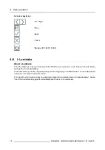
Overview key icons

Left, Right

Menu

Enter

Cancel

Standby (IEC 60417–5009)

4.6

I-Luminate

About I-Luminate

When the display is in power on mode and the OSD menu is not shown, I-Luminate can be activated by
touching the I-luminate/left key.

Unlike other Barco products, especially designed for tomography, in the MDCG-3221, I-Luminate supports
one mode: Full-screen luminance boost.

When touching the I-Luminate key, the display will enter the I-Luminate mode, for approximately 1 minute.
Touch the I-Luminate key again to immediately switch back to normal mode.

18

K5902060 CORONIS 3MP LED DISPLAY 01/10/2015

Summary of Contents for Coronis 3MP LED

Page 1: ...Coronis 3MP LED Display User Guide MDCG 3221 K5902060 04 01 10 2015...

Page 2: ...Barco NV President Kennedypark 35 8500 Kortrijk Belgium Phone 32 56 23 32 11 Fax 32 56 26 22 62 Support www barco com en support Visit us at the web www barco com Printed in Belgium...

Page 3: ...ate 18 5 Advanced operation 19 5 1 OSD menu language 19 5 2 OSD menu automatic close function 19 5 3 Power status indicator light 19 5 4 Key indicator lights 20 5 5 Power lock function 20 5 6 Ethernet...

Page 4: ...7 1 Cleaning instructions 37 8 Important information 39 8 1 Safety information 39 8 2 Environmental information 40 8 3 Regulatory compliance information 42 8 4 EMC notice 43 8 5 Explanation of symbols...

Page 5: ...uard front of screen sensor with backlight ambient light and temperature sensors to optimize image quality and keep it consistent over time Green performance Using energy efficient LED backlights Barc...

Page 6: ...LED Display comes with the display a system tilt and swivel foot this Coronis 3MP LED Display user guide a system CD a DisplayPort cable a DVI cable an USB cable an AC power cord an external power su...

Page 7: ...AND CONNECTORS 2 1 Display front view Overview 1 2 4 5 6 7 3 Image 2 1 Front view 1 I Luminate Left key 5 Power LEDs 2 Right key 6 Ambient light sensor 3 Menu key 7 Bottom downstream USB 4 Standby ke...

Page 8: ...closed Image 2 2 Rear view with closed connector compartment cover 1 Connector compartment cover 3 Foot lock clip 2 Cable duct 4 Tilt swivel foot Connector compartment cover open Image 2 3 Rear view w...

Page 9: ...note below 2 5 VDC 0 5A power output 6 USB upstream connector 3 DisplayPort video input 7 USB downstream connector 4 DVI video input The Ethernet connection is used for maintenance purposes and is not...

Page 10: ...2 Parts controls and connectors 8 K5902060 CORONIS 3MP LED DISPLAY 01 10 2015...

Page 11: ...rix available on my barco com MyBarco My Support Healthcare Com patibility Matrices Barco Systems Compatibility Matrices 3 1 Unlocking the height mechanism To remove the clip 1 Position the display wi...

Page 12: ...e In some cases the image will be rotated automatically in other cases it will not be rotated e g when pixels would be lost after rotation If necessary change the image resolution in the display contr...

Page 13: ...ut selection of the device is automatically done By default the DisplayPort input has priority over the DVI input This can be changed in the OSD menu 1 Connect the DVI or DP of the display controller...

Page 14: ...ble routing channel in the stand of your display Tip The cable straps at the inside of the connector compartment allow you to fix the cables for better shielding of the cables To Reattach the connecto...

Page 15: ...that can support the weight of the display Refer to the technical specifica tions of this display for the applicable weight Overview The panel standard attached to the tilt swivel foot is compatible w...

Page 16: ...page 16 2 Turn on the computer connected to your display If you have properly installed your display and display controller the Windows start up messages will appear once the boot procedure is finishe...

Page 17: ...age A good screen saver displays moving content In case you are working with the same image or an application with static image elements for several hours continuously so that the screen saver is not...

Page 18: ...vailable for activation of the I Luminate fea ture Please refer to I Luminate page 18 for more information The key auto dim function can be disabled in the OSD menus Please refer to Key in dicator lig...

Page 19: ...t the OSD main menu comes up in the bottom right corner of the screen However if no further actions are taken within the following 90 seconds the OSD will disappear again The OSD menu auto exit functi...

Page 20: ...activated by touching the I luminate left key Unlike other Barco products especially designed for tomography in the MDCG 3221 I Luminate supports one mode Full screen luminance boost When touching the...

Page 21: ...sed To enable disable the OSD menu automatic close function 1 Bring up the OSD main menu 2 Navigate to the Configuration User Interface Menu menu 3 Enter the Automatic Close submenu 4 Select Enabled D...

Page 22: ...again To enable disable the power lock function 1 Bring up the OSD main menu 2 Navigate to the Configuration User Interface Controls menu 3 Enter the Power Lock submenu 4 Select Enabled Disabled as de...

Page 23: ...using a non Barco dis play controller If you are using a Barco display controller this communication will au tomatically be done over the connected video cable s To enable disable USB 1 Bring up the...

Page 24: ...ble disable hibernation on your display 1 Bring up the OSD main menu 2 Navigate to the Configuration Power Management menu 3 Enter the Hibernate submenu 4 Select Enabled Disabled as desired and confir...

Page 25: ...iagnostic This mode provides the full calibrated luminance and is intended for using the display for diagnostic purposes Text In this mode the luminance is reduced to approximately half of the luminan...

Page 26: ...ion results in more visible grayscales in the images Barco recommends selecting the DICOM display function for most medical viewing applications User This display function will be automatically select...

Page 27: ...is enabled Please refer to Ambient Light Compensation ALC page 24 to enable ALC The available reading rooms for your Coronis 3MP LED Display are CR DR MAMMO Corresponds to light conditions in diagnos...

Page 28: ...ections Embedded QA will use the front sensor I Guard to measure the necessary luminance levels for either a calibration or compliance test Various settings for both actions can be selected from the d...

Page 29: ...Status Calibration executed When the calibration is executed the following extra information is shown Backlight runtime elapsed since latest calibration display function ambient light compensation re...

Page 30: ...ferences submenu 4 Select reset DICOM calibration to restore the original not corrected DICOM curve 5 17 6 DICOM error threshold About DICOM error threshold The threshold to define the DICOM complianc...

Page 31: ...te to the Configuration Image Sources menu 3 Enter the Display Orientation submenu 4 Select Landscape Portrait Automatic as desired and confirm 5 20 Video input signals About input signals The availab...

Page 32: ...3MP LED Display will automatically assign the correct video encoding settings to the connected video input signals To manually select a video encoding mode 1 Bring up the OSD main menu 2 Navigate to t...

Page 33: ...to 10 bit To manually set EDID timings 1 Bring up the OSD main menu 2 Navigate to the Configuration Image Source menu 3 Enter the Timings submenu 4 Select Refresh Rate Preferred Orientation or Color...

Page 34: ...retrieve the status of your display 1 Bring up the OSD main menu 2 Navigate to the Status menu 3 Enter the Display Image Sources Calibration or Connectivity submenu as desired 32 K5902060 CORONIS 3MP...

Page 35: ...the display follow the instruction to replace the protection buffer to prevent damage to the display Overview of the packaging 1 2 3 4 5 6 7 8 Image 6 1 Packaging 1 Bottom box 5 Box Power supply cabl...

Page 36: ...nlocking the height mech anism page 9 3 Very important Tilt the panel away from the foot before changing the orientation 4 Turn the panel counterclockwise to put the panel in landscape orientation see...

Page 37: ...buffer in the box 3 Put the display together with the protection buffer see Replacing the protection buffer page 34 in the dedicated cavity of the bottom buffer 4 Put the top buffer on top of the dis...

Page 38: ...6 Repackaging instructions 36 K5902060 CORONIS 3MP LED DISPLAY 01 10 2015...

Page 39: ...l solvents at higher concentration 5 Strong alkalis lye strong solvents Acid Detergents with fluoride Detergents with ammonia Detergents with abrasives Steel wool Sponge with abrasives Steel blades Cl...

Page 40: ...7 Cleaning your display 38 K5902060 CORONIS 3MP LED DISPLAY 01 10 2015...

Page 41: ...atient care equipment Equipment primarily for use in a health care facility that is intended for use where contact with a patient is unlikely no applied part The equipment may not be used with life su...

Page 42: ...tallation Place the device on a flat solid and stable surface that can support the weight of at least 3 devices If you use an unstable cart or stand the device may fall causing serious injury to a chi...

Page 43: ...a Administration on Control of Pollution Caused by Electronic Information Products Also called RoHS of Chinese Mainland the table below lists the names and contents of toxic and or hazardous substance...

Page 44: ...logo The number inside the EFUP logo that Barco uses please refer to the photo is based on the Standard of Electronic Information Products Environmental Friendly Use Period of Chinese Mainland 10 Chin...

Page 45: ...help Changes or modifications not expressly approved by the party responsible for compliance could void the user s authority to operate the equipment Canadian notice This ISM device complies with Can...

Page 46: ...agnetic environment guidance Electrostatic discharge ESD IEC 61000 4 2 6kV contact 8kV air 6kV contact 8kV air Floors should be wood concrete or ceramic tile If floors are covered with synthetic mater...

Page 47: ...Field strengths from fixed RF transmitters as determined by an electromagnetic site survey 3 should be less than the compliance level in each frequency range 4 Interference may occur in the vicinity...

Page 48: ...frequency of transmitter Rated maximum output power of transmitter 5 W 150kHz to 80MHz d 1 2 P 80MHz to 800MHz d 1 2 P 800MHz to 2 5GHz d 2 3 P 0 01 0 12 0 12 0 23 0 1 0 38 0 38 0 73 1 1 2 1 2 2 3 10...

Page 49: ...ng to the UL regulations for Canada and US Indicates the device is approved according to the UL Demko regulations Indicates the device is approved according to the CCC regulations Indicates the device...

Page 50: ...ording to the European WEEE Waste Electrical and Electronic Equipment directive Indicates Direct Current DC Indicates Alternating Current AC Stand by Equipotentiality Symbols on the box On the box of...

Page 51: ...o provide you with the most accurate and usable documentation possible if you discover errors please let us know Barco software products are the property of Barco They are distributed under copyright...

Page 52: ...PPU Yes Ambient Light Compensation ALC Yes Backlight Output Stabilization BLOS Yes I Guard Yes Maximum luminance 1700 cd m typical DICOM calibrated luminance ULT off 600 cd m Contrast ratio ULT off 1...

Page 53: ...950 1 2005 A1 2009 2ND EDITION IEC 60601 1 2005 A1 2012 ANSI AAMI ES 60601 1 2005 C1 2009 A1 2012 CAN CSAC22 2 No 60601 1 08 2008 DEMKO EN 60601 1 2006 EN 60601 1 2 2007 CCC GB9254 2008 GB4943 1 2011...

Page 54: ...IABILITY MORE INFORMATION DETAILS IS TO BE FOUND IN EACH SPECIFIC OPEN SOURCE LICENSE With respect to GPL LGPL or similar licenses with regard to corresponding source code access and automatic license...

Reviews: