background image

5. Random Access

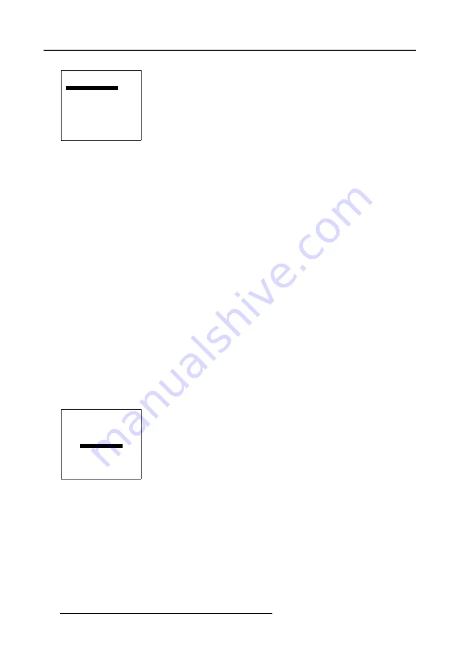
5. Push the cursor key

or

to highlight

TDR Top

.

TRANSPORT DELAY

TOP MODE

[MANUAL]

TDR TOP

200

BOTTOM MODE [AUTOMATIC]
TDR BOTTOM

1200

Menu 5-127

6. Push the

cursor key to set the Top Transport Delay to the maximum value in the set up, in this case set the Top Transport

Delay manually to 250.

7. Repeat step 3 to 6 for projector 3.

8. Press

EXIT

to return to the

Guided Geometry Map

menu.

How to adjust the Bottom Transport Delay?

The Bottom Transport Delay is only used in combination with complex distortion settings, this is best done by qualified service
personnel, changing these settings may seriously affect the performance of the projector.

5.5.7.9

Blanking

Overview

Starting up the Blanking menu

Blanking Active On

Blanking Shape Start up

Blanking Shape selections

Blanking adjustment

5.5.7.9.1

Starting up the Blanking menu

What can be done with Blanking ?

Blanking adjustments affect only the edges of the projected image and are used to frame the projected image on the screen and to
hide unwanted image information (or noise).

How to Start up Blanking ?

1. Push the cursor key

or

to highlight

Blanking/Soft Edge

within the

Guided Geometry map

menu.

GUIDED EDIT

3x3
5x5
9x9

17x17
SHIFT

TRANSPORT DELAY

BLANKING/SOFT EDGE

RESET

Select with

or

then <ENTER>

<EXIT> to return

Menu 5-128

2. Press

ENTER

to select.

134

R5976707 REALITY SIM 6 ULTRA II 01/02/2005

Summary of Contents for BarcoReality SIM 6 Ultra II

Page 1: ...Reality SIM 6 Ultra II Owner s Manual R9040152 R5976707 01 01 02 2005 ...

Page 2: ...one 1 937 372 7579 Fax 1 937 372 8645 E mail eis barco com Visit us at the web www eis barco com Barco nv Simulation Products Noordlaan 5 B 8520 Kuurne Phone 32 56 36 82 11 Fax 32 56 36 84 86 E mail info barco com Visit us at the web www barco com Printed in Belgium ...

Page 3: ...marks Brand and product names mentioned in this manual may be trademarks registered trademarks or copyrights of their respective holders All brand and product names mentioned in this manual serve as comments or examples and are not to be understood as advertising for the products or their manufactures Federal Communications Commission FCC Statement This equipment has been tested and found to compl...

Page 4: ......

Page 5: ...pad 29 4 2 Terminology overview 29 4 3 Operating the projector 31 4 3 1 Switching on 31 4 4 Quick setup adjustments 32 4 4 1 Quick lens Adjustment 32 4 4 2 Quick on Screen Color Change 33 4 5 Using the RCU 34 4 6 Projector Address 36 4 6 1 Controlling the projector 36 4 6 2 Displaying and Programming addresses 37 4 7 Controlling the projector 37 5 Random Access 39 5 1 Random Access Overview 40 5 2...

Page 6: ...95 5 5 7 5 2 Selecting the 9x9 H side Level 7 96 5 5 7 5 3 Adjusting the 9x9 H side Level 7 97 5 5 7 5 4 Selecting the 9x9 V side Level 7 99 5 5 7 5 5 Adjusting the 9x9 V side Level 7 100 5 5 7 5 6 Selecting the 9x9 Center Level 8 102 5 5 7 5 7 Adjusting the 9x9 Center Level 8 103 5 5 7 5 8 Selecting the 9x9 Quadrant Level 9 105 5 5 7 5 9 Adjusting the 9x9 Quadrant Level 9 106 5 5 7 5 10 Selecting...

Page 7: ...rt up 169 6 4 Input Slots 169 6 5 No signal 170 6 5 1 Changing the background color 171 6 5 2 Changing the shutdown setting 171 6 5 3 Changing the shutdown time 172 6 6 Barco logo 172 6 7 Lens Adjustment 173 6 8 Menu Position 174 6 9 800 Peripheral 175 6 9 1 Defining the Output module of the RCVDS05 175 6 9 2 Defining the communication protocol of the RCVDS05 176 6 10 Configuration 177 6 11 OSD Co...

Page 8: ...9 Source Numbers 81 86 and 91 96 211 9 1 Projector without any 800 peripheral connected 211 9 2 Projector with a 800 peripheral connected 211 9 2 1 Source numbers 91 96 211 9 2 2 Source numbers 81 86 212 10 Cleaning the Dustfilter 213 10 1 Cleaning 213 Index 215 4 R5976707 REALITY SIM 6 ULTRA II 01 02 2005 ...

Page 9: ... shipping carton and place it on a table Save the original shipping carton and packing material they will be necessary if you ever have to ship your projector For maximum protection repack your projector as it was originally packed at the factory CAUTION Never transport the projector with the lens mounted on it Always remove the lens before transporting the projector 1 2 Lens Packaging Way of Pack...

Page 10: ...5 4 mm 187 2 202 4 371 2 53 5 29 6 53 5 97 6 120 2 245 1 152 6 152 6 6 107 5 min 12 max 24 Image 1 2 Front view dimensions projector 46 82 7 211 4 169 5 139 6 14 148 9 380 6 526 8 60 43 124 1 217 2 147 8 124 4 42 Image 1 3 Side view dimensions projector 6 R5976707 REALITY SIM 6 ULTRA II 01 02 2005 ...

Page 11: ...1 Packaging and Dimensions 184 4 368 7 Image 1 4 Top view dimensions projector R5976707 REALITY SIM 6 ULTRA II 01 02 2005 7 ...

Page 12: ...1 Packaging and Dimensions 8 R5976707 REALITY SIM 6 ULTRA II 01 02 2005 ...

Page 13: ...of screen to use are critical to the optimum use of the projection system Max ambient temperature 40 C or 104 F Min ambient temperature 0 C or 32 F The projector will not operate if ambient air temperature falls outside this range 0 C 40 C or 32 F 104 F Storage temperature 35 C to 65 C 25 6 F to 149 F Humidity Conditions Storage 0 to 98 RH Non condensing Operation 0 to 95 RH Non condensing Environ...

Page 14: ... ceiling lights and a method of dimming those lights to an acceptable level is also important Too much ambient light will wash out of the projected image This appears as less contrast between the darkest and lightest parts of the image With bigger screens the wash out becomes more important As a general rule darken the room to the point where there is just sufficient light to read or write comfort...

Page 15: ...t feet and middle of the lens Value to be subtracted from B to obtain the correct installation position A value is a constant value for all screen widths and type of lenses A 124 1 mm or 4 89 inch CD Total distance between projector and ceiling or projector and floor SW Screen width SH Screen height image height PD Projector distance distance between screen and projector 2 4 Lenses Overview Lenses...

Page 16: ... 0 984 34 10 SW QFD 1 4 2 1 1 PDmin 1 44 x SW 0 0287 0 022 SW PDmax 2 20 x SW 0 01 0 020 SW PDmin 1 44 x SW 1 13 34 10 SW PDmax 2 20 x SW 0 39 31 00 SW QFD 2 1 3 0 1 PDmin 2 13 x SW 0 10 0 056 SW PDmax 2 90 x SW 0 10 0 0745 SW PDmin 2 13 x SW 3 937 86 80 SW PDmax 2 90 x SW 3 937 115 48 SW QFD 3 4 4 5 1 PDmin 3 374 x SW 0 115 0 0575 SW PDmax 4 433 x SW 0 133 0 0556 SW PDmin 3 374 x SW 4 53 89 13 SW...

Page 17: ... SIM6 projector How to install Follow the next procedure 1 Open the lens cover of the projector by pivoting it up and take it off Image 2 2 2 Pull the lens locks levers backwards to open the lens locks Image 2 3 3 Put the lens on the lens holder Image 2 4 4 Push the lens locks back in position and lock the levers 5 Plug the wires of the motor unit into the connector R5976707 REALITY SIM 6 ULTRA II...

Page 18: ...Warning Do not wipe back and forwards across the lens surface as this tends to grind dirt into the coating 3 Do not leave cleaning cloth in either an open room or lab coat pocket as doing so can contaminate the cloth 4 If smears occur when cleaning lenses replace the cloth Smears are the first indication of a dirty cloth WARNING Do not use fabric softener when washing the cleaning cloth or softene...

Page 19: ...nstallation Guidelines 2 Lift up the top side of the cover at the same time 3 Insert the batteries as indicated in the RCU 4 Put the battery cover on its place R5976707 REALITY SIM 6 ULTRA II 01 02 2005 15 ...

Page 20: ...2 Installation Guidelines 16 R5976707 REALITY SIM 6 ULTRA II 01 02 2005 ...

Page 21: ...nput is auto ranging from 90 to 240 VAC Fuses For continued protection against fire hazard refer replacement to qualified service personnel ask to replace with the same type of fuse T10 AH 250V 3 2 Switching on How to switch on 1 Press the power switch to switch on the projector When 0 is visible the projector is switched off When 1 is visible the projector is switched on The projector starts in s...

Page 22: ...e indication while running The dual lamp power mode is taken into account to calculate the lamp run time limit The lamp run time warning will only be displayed when the time is exceeding this limit A warning message will be displayed with the exact run time x displayed on the screen This message is displayed only at the start up of the projector Press the EXIT button on the RCU or keypad to remove...

Page 23: ...his period the LED display will show a jumping square with a dash After one minute two dashes will be displayed and the projector can restart 3 4 Switching off How to switch off the projector To switch off the projector handle as follow 1 Press STANDBY key for 2 seconds When the message Saving data please wait is displayed do not press any longer on the STANDBY key otherwise the projector will res...

Page 24: ... 2 Input Selection Mode What can be done with the Input Selection Mode This Input Selection Mode can be set AUTOMATIC or MANUAL When AUTOMATIC is selected in the Input slots menu by starting up the projector it searches for an input source by scanning the inputs If only one source is found this source will be projected If different sources are found the priority is as follow 1 5 Cable input 2 Comp...

Page 25: ...isplayed INSTALLATION INPUT SLOTS NO SIGNAL BARCO LOGO LENS MENU POSITION CENTER 800 PERIPHERAL MORE Select with or then ENTER EXIT to return Menu 3 4 4 Push the cursor key or to highlight Input Slots INSTALLATION INPUT SLOTS NO SIGNAL BARCO LOGO LENS MENU POSITION CENTER 800 PERIPHERAL MORE Select with or then ENTER EXIT to return Menu 3 5 5 Press ENTER to select The Input Slots menu will be disp...

Page 26: ...a RCVDS05 it is recommended to use a 5 Cable Output module in the RCVDS The outputs of this module have to be connected to the 5 Cable Input Input Slot 1 of the projector To switch the projector in the 5 Cable mode see chapter Installation mode 3 6 4 Input 1 Which signals can be connected to Input 1 Connector name Input Signal R G B H V RGBHV R G B H V RGBS R G B S RGsB R Gs B Composite Video1 Vid...

Page 27: ... the Input Slot menu To change the signal format 1 Press the ADJUST or ENTER key to start up the Adjustment mode The Adjustment Mode menu will be displayed ADJUSTMENT MODE Select a path from below RANDOM ACCESS INSTALLATION SERVICE Select with or then ENTER EXIT to return Menu 3 8 2 Push the cursor key or to highlight Installation ADJUSTMENT MODE Select a path from below RANDOM ACCESS INSTALLATION...

Page 28: ...he signal priority 8 Press EXIT several times to leave the adjustment mode Possible indications on the input slot menu RGB HS VS RGB analog signals separate sync is horizontal and vertical sync RGB CS RGB analog signals separate sync is composite sync RGB CV RGB analog signals separate sync is composite video or tri level sync RGB SOG RGB analog signals sync on green is composite sync VIDEO1 S VID...

Page 29: ...RED 2 GREEN 3 BLUE 4 loop through to monitor 5 ground 6 ground 7 ground 8 ground 9 loop through to monitor 10 ground 11 loop through to monitor 12 loop through to monitor 13 horizontal composite sync 14 vertical sync 15 loop through to monitor How to select Input 2 1 Press key 2 on the RCU or local keypad 3 6 6 Input 3 Optional This Composite Video Input is only available when the Optional Video D...

Page 30: ...tor 1x BNC or Cinch 1 0 Vpp 3dB SDI SDO S VIDEO COMPUTER IEEE 1394 MOUSE MONITOR RS232 IN RS232 OUT AUDIO IN AUDIO IN AUDIO IN AUDIO IN COMM PORT RC C B A 5 6 4 10 100 Base T 2 1 3 VIDEO R G B H C V TV Tuner e g Marco Polo DVD Source VCR Composite Video Image 3 7 Connecting to Input 3 How to select Input 3 1 Press key 3 on the RCU or local keypad 3 6 7 Input 4 Optional This Composite Video Input i...

Page 31: ...3dB 4 Chrominance 282 mVpp 3dB How to select Input 4 1 Press key 4 on the RCU or local keypad 3 7 Communications connections Overview RS232 3 7 1 RS232 Application 1 Remote control easy adjustment of projector via an IBM PC or compatible or MAC connection allow storage of multiple projector configurations and set ups wide range of control possibilities address range from 0 to 255 2 data communicat...

Page 32: ...3 Connections 28 R5976707 REALITY SIM 6 ULTRA II 01 02 2005 ...

Page 33: ...the user to control the projector remotely This remote control is used for source selection control adaptation and set up It includes automatic storing of picture controls Bright ness Sharpness and settings Other functions of the remote control are switching between stand by and operational mode switching to pause blanked picture full power for immediate restarting direct access to all connected s...

Page 34: ... for immediate restarting 6 STBY standby button to start projector when the power switch is switched on and to switch off the projector without switching off the power switch Attention Switching to Standby When the projector is running and you want to go to standby press the standby key for 2 seconds until the message Saving data please wait is displayed Do not press any longer on the standby key ...

Page 35: ...up cursor key down key down cursor key right key right cursor key left key left 17 EXIT to leave the adjustment mode or to scroll upwards when in the adjustment mode 18 RC operation indication lights up when a button on the remote control is pressed This is a visual indicator to check the operation of the remote control Table 4 1 4 3 Operating the projector 4 3 1 Switching on How to switch on 1 Pr...

Page 36: ...OL 9 0 7 8 5 6 3 4 1 2 COLOR PHASE SHARPN TINT BRIGHTN STANDBY ENTER TEXT EXIT PAUSE 2 1 4 3 5 6 8 0 9 7 CONTRAST Stand by key Image 4 3 4 4 Quick setup adjustments Overview Quick lens Adjustment Quick on Screen Color Change 4 4 1 Quick lens Adjustment What can be done For a quick lens adjustment press the key on the RCU to display immediately the lens menu 32 R5976707 REALITY SIM 6 ULTRA II 01 02...

Page 37: ...isplayed 2 Press ENTER The shift menu will be displayed Or Push the cursor key or to shift the image up or down and or to shift the image left or right 3 When finished press EXIT key to return or ENTER to continue to zoom focus 4 4 2 Quick on Screen Color Change What can be done For quick change of the on screen color of the highlighted items The highlighted items on the menus can be displayed in ...

Page 38: ...ACTIVE 3D CONF MORE Select with or then ENTER EXIT to return Menu 4 4 6 Push the cursor key or to highlight OSD COLOR The OSD color menu will be displayed OSD COLOR HIGHTLIGHTED ITEM RED GREEN YELLOW Select with or then ENTER EXIT to return Menu 4 5 7 Push the cursor key or to highlight the desired color 8 Press ENTER to activate 4 5 Using the RCU Pointing to the reflective screen 1 Point the fron...

Page 39: ...232 IN RS232 OUT AUDIO IN AUDIO IN AUDIO IN AUDIO IN COMM PORT RC C B A R G B H C V 5 6 2 1 4 3 10 100 Base T Image 4 5 RCU Hardwired to Remote Input Directly to one of the IR sensors of the projector When using the wireless remote control make sure you are within the effective operating distance 30m 100ft in a straight line The remote control unit will not function properly if strong light strike...

Page 40: ... address Default address Projector will always execute the command coming from a RCU programmed with that common address Why a projector address As more than one projector can be installed in a room the separate projector should be separately addressable with an RCU or computer There for each projector has its own address Set up an individual Projector Address The set up of a projector address can...

Page 41: ...dress is not entered within 5 seconds the RCU returns to its default address zero address and control all projectors in the room How to Program an Address into the RCU 1 Press the Address key recessed key on the RCU with a pencil 2 Enter the address with the digit buttons within 5 seconds after pushing the address key Note That address can be any digit between 0 and 9 4 7 Controlling the projector...

Page 42: ...ress Freez to freeze the displayed image The Pause Key When the Pause key is pressed the image projection is stopped a blue or black screen will be displayed and the projector remains with full power for immediate restart The sound is not interrupted The display on front of the projector will show a P To restart the image Press Pause key Press EXIT key Select a source number The Selection key See ...

Page 43: ...5 Random Access 5 RANDOM ACCESS Overview Random Access Overview Random Access Start up File Service Picture Tuning Geometry Geometry WARP 6 not activated R5976707 REALITY SIM 6 ULTRA II 01 02 2005 39 ...

Page 44: ...o LCD Speed o LCD Speed R G o LCD Speed B G Color Temperature o Projector White o Computer 9300K o Video 6500K o Film 5400K o Broadcast 3200K o Custom Balance Gamma Input Balance o White Balance o Black Balance o Default Windowing o Blanking o Top o Bottom o Left o Right o Reset o Shift o Size o Geo Soft Edge On Off o Aspect Ratio o 5 4 o 4 3 o 16 9 2 This function will be implemented in the next ...

Page 45: ...estore To 3x3 o Restore To 5x5 o Restore To 9x9 o Blanking Soft Edge Optional o Soft Edge Optional o All o Full Reset Free Edit Rename Copy Delete Geometry When the WARP 6 option is not activated Size Shift Keystone Blanking Soft Edge 5 2 Random Access Start up How to start up 1 Push the cursor key or to highlight Random Access ADJUSTMENT MODE Select a path from below RANDOM ACCESS INSTALLATION SE...

Page 46: ...rresponding to the most used sources When the new source corresponds with one of these files the file can be loaded and saved for future use When there is a little difference the file can also be loaded and then edited until the source specs are reached File loading can be done automatically Files with a in front of the file name are temporary files These files will be deleted when switching to an...

Page 47: ...g on the installed filter LOAD FILE FILTER LIST All Filename Scr resolution xga_60 s01 1 1024x768 xga_60 c01 1 1024x760 xga_60 c02 1 1024x760 xga_60 c03 1 1024x760 Active file xga_60 c04 Select with or ENTER to accept EXIT to return Menu 5 5 Changing the filter setting 1 Push the cursor key or to highlight filter list 2 Press ENTER to toggle the annotation between brackets ALL all files that can b...

Page 48: ...o confirm the new creation or EXIT to return to the load file menu During a load file the actual file is displayed next to the indication Active file When scrolling through the files the image will be adapted according to the settings of the selected file on line adaptation The image is not perfect If the displayed image is not correct after selecting the best fitting file go to the Edit menu sele...

Page 49: ...e upper right corner EDIT FILE xga_60 c02 HORIZONTAL TOTAL 1344 PIXELS ACTIVE 1024 PIXELS START 266 PIXELS PERIOD 16 625 µs VERTICAL FIELD TOTAL 800 LINES ACTIVE 760 LINES START 37 LINES AMDS INTL OFF STILL OFF READ AMDS OPTIONS ENTER EXIT Menu 5 10 5 3 5 2 Changing the settings Different methods The 3 different methods to change a setting will be described hereafter These methods are with the num...

Page 50: ...values for the item in the Edit file menu Horizontal Total Pixels If the value for Horizontal Total Pixels is wrong sampling mistakes small vertical bars with noisy and unsharp data in the projected image will be seen in the image Select Total and adjust the pixel quantity Adjust for zero bars hint if the number of bars increase adjust in the other direction Active Pixels The Active Pixels determi...

Page 51: ...tefacts Read AMDS AMDS Automatic Mode Detection Synchronization During the installation of a file with LOAD the system automatically measured the horizontal period the total vertical lines and the interlaced mode When selecting Read AMDS the system remeasures the above indicated items How to install the correct settings for the options in the Edit file menu EDIT FILE OPTIONS Source number 1 Clamp ...

Page 52: ...select The Rename file menu will be displayed with the selected file name already filled in leave in the From file name area and in the To file name area The first character in the To file name area is highlighted Changing the characters 1 Push the cursor keys or to select the desired character RENAME FILE From file name xga_60 c02 To file name demo c02 Select with or Reprogram with or ENTER to co...

Page 53: ...select The Copy file menu will be displayed with the selected file name already filled in leave in the From file name area and in the To file name area The first character in the To file name area is highlighted Changing the characters 1 Push the cursor key or to select the desired character COPY FILE From file name xga_60 c02 To file name demo c02 Select with or Reprogram with or ENTER to confirm...

Page 54: ...cept EXIT to return Menu 5 19 3 Push the cursor key or to select a file name 4 Press ENTER to select If all is selected your password has to be entered before all files will be deleted A confirmation menu Delete file name is displayed CONFIRM DELETE FILE Delete file xga_60 c02 Select with or Reprogram with or ENTER to confirm EXIT to return Menu 5 20 5 Press ENTER to delete the file press EXIT if ...

Page 55: ... File Sort setting is default set to NAME NAME The files in the list will be sorted on the file name INDEX The files in the list will be sorted on the file extension File Load 1 Push the cursor key or to highlight File Load FILE OPTIONS FILE SORT NAME FILE LOAD AUTOMATIC SERIAL FILE LOAD OFF FIELD STRETCH OFF Select with or then ENTER EXIT to return Menu 5 24 2 Press ENTER to toggle between AUTOMA...

Page 56: ...or the lack off bandwidth on some older IG s Complicated source content will result in long render times the field stretch option will give the IG extra time to render the source content before sending the next source field According to the complexity of the content this extra time will vary in time resulting in a variable vertical field time The projector s field stretch option allows the project...

Page 57: ...tion is not installed Overview Starting up the Motion Compensation LCD speed LCD speed R G LCD speed B G What can be done Motion Compensation allows to change the response time of the LCD panels The following options can be adjusted LCD speed LCD speed R G LCD speed B G 5 4 2 1 Starting up the Motion Compensation How to start up 1 Push the cursor key or to highlight Motion compensation PICTURE TUN...

Page 58: ... B G Select with or then ENTER EXIT to return Menu 5 30 2 Press ENTER to select A sliderbow will be displayed 3 Push the cursor key or to set the LCD speed 5 4 2 3 LCD speed R G What can be done The response time of the Red LCD compared to the Green LCD can be modified Range 0 2 with steps of 0 125 Default 1 00 How to set the LCD speed R G 1 Push the cursor key or to highlight LCD speed R G MOTION...

Page 59: ...layed 3 Push the cursor key or to set the Blue LCD speed 5 4 3 Color Temperature Available Color temperatures Projector white Broadcast 3200K Film 5400K Video 6500K Computer 9300K How to start up 1 Push the cursor key or to highlight Color Temperature PICTURE TUNING MOTION COMPENSATION COLOR TEMPERATURE GAMMA INPUT BALANCE WINDOWING Select with or then ENTER EXIT to return Menu 5 33 2 Press ENTER ...

Page 60: ... 3 Change the gamma value by pushing the cursor key or until the desired value is reached Note Default value of gamma 1 9 4 Press EXIT to return to the Picture Tuning menu 5 4 5 Input Balance Why adjusting the input balance The input balance is normally correct adjusted in the factory But due to signal distribution or signal transmission outputs a color imbalance can be the result This imbalance c...

Page 61: ...st the Black Balance 1 Generate a full black image on the source Image 5 3 Full black image on the source 2 Push the cursor key or to highlight Black Balance and press ENTER to select INPUT BALANCE WHITE BALANCE BLACK BALANCE DEFAULT Select with or then ENTER EXIT to return Menu 5 37 3 Use the cursor keys and to lower the Black Level of the Blue and Red color 4 Use the Brightness or key to adjust ...

Page 62: ...image on the source Image 5 5 Full white image on the source 2 Push the cursor key or to highlight White Balance and press ENTER to select INPUT BALANCE WHITE BALANCE BLACK BALANCE DEFAULT Select with or then ENTER EXIT to return Menu 5 38 3 Use the cursor keys and to lower the Gain of the Blue and Red color 4 Use the Contrast or key to adjust the Gain of the Green Color until there is 50 noise vi...

Page 63: ... select INPUT BALANCE WHITE BALANCE BLACK BALANCE DEFAULT Select with or then ENTER EXIT to return Menu 5 39 The input balance is set to the default factory preset 5 4 6 Windowing 5 4 6 1 Starting Up Windowing How to Start Up the Windowing menu 1 Push the cursor key or to highlight Windowing PICTURE TUNING MOTION COMPENSATION COLOR TEMPERATURE GAMMA INPUT BALANCE WINDOWING Select with or then ENTE...

Page 64: ... Up Blanking Windowing 1 Push the cursor key or to highlight Blanking WINDOWING BLANKING SHIFT SIZE GEO SOFT EDGE ON ASPECT RATIO 4 3 Select with or then ENTER EXIT to return Menu 5 42 2 Press ENTER to select The Blanking menu will be displayed BLANKING TOP BOTTOM LEFT RIGHT RESET Select with or then ENTER EXIT to return Menu 5 43 How to use the Blanking Windowing adjustment 1 Push the cursor key ...

Page 65: ...ck out the side s of the image Image 5 8 Blanking Windowing adjustment How to reset the Blanking adjustment s 1 Push the cursor key or to highlight Reset BLANKING TOP BOTTOM LEFT RIGHT RESET Select with or then ENTER EXIT to return Menu 5 45 2 Press ENTER to reset all blanking adjustments R5976707 REALITY SIM 6 ULTRA II 01 02 2005 61 ...

Page 66: ...r key or to highlight Shift WINDOWING BLANKING SHIFT SIZE GEO SOFT EDGE ON ASPECT RATIO 4 3 Select with or then ENTER EXIT to return Menu 5 46 2 Press ENTER to select A barscale indication will be displayed H SHIFT 0 0 Image 5 9 Horizontal Shift barscale 3 Push the cursor key or to shift the image horizontally Image 5 10 Horizontal Shift Windowing adjustment 4 Push the cursor key or to shift the i...

Page 67: ...settings of the image How to Start Up the Size adjustment 1 Push the cursor key or to highlight Size WINDOWING BLANKING SHIFT SIZE GEO SOFT EDGE ON ASPECT RATIO 4 3 Select with or then ENTER EXIT to return Menu 5 47 2 Press ENTER to select A barscale indication will be displayed H SIZE 100 Image 5 12 H Size barscale indication 3 Push the cursor key or to adjust the horizontal size of the image R59...

Page 68: ... are applied on all sources source files With the Geo Soft Edge toggle it is possible to disable the soft edge settings for the current source file Geo Soft Edge is default set to On How to change the Geo Soft Edge Setting 1 Push the cursor key or to highlight Geo Soft Edge WINDOWING BLANKING SHIFT SIZE GEO SOFT EDGE ON ASPECT RATIO 4 3 Select with or then ENTER EXIT to return Menu 5 48 2 Press EN...

Page 69: ...rojectors can be used in a wide variety of curved screen applications ranging from straightforward cylindrical displays to the wildest shapes that can be imagined by pre distorting the image inside the projector a correct geometry can be achieved on curved screens without requiring additional computational power on the IG s side Since WARP 6 is integrated in the BarcoReality SIM6 Ultra II Pixel Ma...

Page 70: ...character t geometry preset file first character g geometry user file The second and third character is used for a following number file index The file index for custom files 00 to 63 Table 5 10 5 5 4 Setting up a new Geometry file How to set up a new Geometry file 1 Load the start up file t_nodist t01 2 Select the EDIT menu and perform the necessary adjustments 3 When leaving the EDIT menu a new ...

Page 71: ...file from the list the geometry adjustments will be applied only when selecting a file by pressing the ENTER key ON The geometry adjustments are already applied when highlighting a file from the list this will require some processing time from the projector when scrolling through the list of available files How to Load a file 1 When starting a new set up If yes Push the key to highlight the t_nodi...

Page 72: ...roup of grid points these can be shifted to the desired location Each level will interact with other levels in a hierarchic way adjusting a grid point on a certain hierarchic level will affect grid points in the levels underneath corner Level 1 Level 2 Level 3 side bow center 3x3 H side Level 4 Level 4 Level 5 Level 6 Level 7 Level 8 Level 10 Level 11 Level 11 Level 12 Level 13 Level 14 Level 15 L...

Page 73: ... point a second box with a dotted line will indicate the interaction zone on the levels underneath Selection Box Interaction Box Image 5 16 Selection Box Interaction Box On top of this hierarchy is a matrix with 3 x 3 points adjusting grid points on level 1 corners will affect level 2 till 15 Image 5 17 Level 1 3x3 corner R5976707 REALITY SIM 6 ULTRA II 01 02 2005 69 ...

Page 74: ...sted in the menu interface 5 5 7 2 Starting up the Guided Edit mode How to Start up the Guided Edit mode 1 Push the cursor key or to highlight Guided Edit in the Geometry Files menu GEOMETRY FILES LOAD GUIDED EDIT FREE EDIT RENAME COPY DELETE Select with or then ENTER EXIT to return Menu 5 55 2 Press ENTER to select The Guided Geometry Map menu will be displayed GUIDED EDIT 3x3 5x5 9x9 17x17 SHIFT...

Page 75: ...ORT DELAY BLANKING SOFT EDGE RESET Select with or then ENTER EXIT to return Menu 5 57 2 Press ENTER to select The Geometry Distortion menu will be displayed GEOMETRY DISTORTION corners 3x3 col 0 row 0 pixels x 0 y 0 subpixels x 0 y 0 AxisLink ON Menu 5 58 5 5 7 3 2 Selecting the 3x3 Corners Level 1 What can be done With the 3x3 Corner selection it is possible to adjust the basic geometry and size ...

Page 76: ... 7 7 7 7 9 9 9 9 9 9 9 9 9 9 9 9 9 9 9 9 8 8 8 8 8 8 8 8 Image 5 19 3x3 Corner Level 1 selections The COL ROW Column and Rows indicator4 will show the corresponding position of the selected Corner and an indication box will be displayed on the screen 5 5 7 3 3 Adjusting the 3x3 Corners Level 1 To change a setting only the method using the arrow keys is mentioned in the following procedures the pro...

Page 77: ... On and Off 1 Start with a non distorted image assume the left top corner is selected 0 0 Image 5 20 Non distorted image 2 Shift the left top corner 300 pixels to the left 300 0 X 300 Image 5 21 Shift the left top corner 300 pixels to the left R5976707 REALITY SIM 6 ULTRA II 01 02 2005 73 ...

Page 78: ...edges of the distorted image this will result in an quick adjustment when dealing with complex setups AxisLink OFF The coordinate system used for the adjustment is absolute Y 300 225 300 300 300 X Y Y 3 0 0 X Y X AxisLink OFF AxisLink ON Y X Y Image 5 22 Shift the left corner 300 pixels downwards 74 R5976707 REALITY SIM 6 ULTRA II 01 02 2005 ...

Page 79: ... shift the selected Corner in a horizontal way Image 5 23 3x3 Corner Level 1 Adjustment 3 Push the cursor key or to select pixel y 0 in the Geometry Distortion menu GEOMETRY DISTORTION corners 3x3 col 0 row 0 pixels x 0 y 0 subpixels x 0 y 0 AxisLink ON Menu 5 61 4 Push the cursor key or to coarse shift the selected Corner in a vertical way Follow this procedure in a similar way to adjust any desi...

Page 80: ...5 Use the subpixel adjustments to fine shift the selected corners 6 Continue with the 3x3 Side Bow adjustment or press EXIT to return to the Guided Geometry Map menu 5 5 7 3 4 Selecting the 3x3 Side Bows Level 2 What can be done With the 3x3 Side Bow selection it is possible to apply a bow shaped pre distortion on the projected image perform a coarse linearity adjustment off the projected image 76...

Page 81: ...15 14 15 11 13 13 13 13 13 13 13 13 11 15 14 15 13 15 14 15 12 15 14 15 13 15 14 15 11 14 14 14 14 14 14 14 14 11 15 14 15 13 15 14 15 12 15 14 15 13 15 14 15 11 11 11 11 11 11 11 11 11 10 10 10 10 10 10 10 10 10 10 10 10 10 10 10 10 1 2 1 2 3 2 1 2 1 4 4 4 6 5 6 4 4 6 5 6 4 4 4 5 5 7 7 7 7 7 7 7 7 7 7 7 7 7 7 7 7 9 9 9 9 9 9 9 9 9 9 9 9 9 9 9 9 8 8 8 8 8 8 8 8 Image 5 26 3x3 Side Bow Level 2 sele...

Page 82: ...5 7 3 6 Linearity adjustment using 3x3 Side Bows The Linearity adjustment is best done when a reference test pattern is projected on the screen By pressing the key on the RCU an internal hatch pattern is projected instead of the image data How to perform a linearity adjustment by using the 3x3 Side Bows We assume the side bow on top is selected 1 Push the cursor key or to select pixel x 0 in the G...

Page 83: ...ent 4 Use the subpixel adjustments to fine shift the selected Side Bows 5 Continue with the 3x3 Center adjustment or press EXIT to return to the Guided Geometry Map menu 5 5 7 3 7 Selecting the Center Level 3 What can be done With the 3x3 Center selection it is possible to perform a coarse bow correction on the projected image How to select the 3x3 Center 1 Push the cursor key or to to highlight t...

Page 84: ... 15 14 15 13 15 14 15 11 11 11 11 11 11 11 11 11 10 10 10 10 10 10 10 10 10 10 10 10 10 10 10 10 1 2 1 2 3 2 1 2 1 4 4 4 6 5 6 4 4 6 5 6 4 4 4 5 5 7 7 7 7 7 7 7 7 7 7 7 7 7 7 7 7 9 9 9 9 9 9 9 9 9 9 9 9 9 9 9 9 8 8 8 8 8 8 8 8 Image 5 29 3x3 Center Level 3 selections The COL ROW Column and Rows indicator will show the corresponding position of the selected Center and an indication box will be disp...

Page 85: ...r key or to select pixel y 0 in the Geometry Distortion menu GEOMETRY DISTORTION center 3x3 col 8 row 8 pixels x 0 y 0 subpixels x 0 y 0 AxisLink ON Menu 5 67 4 Push the cursor key or to coarse shift the Center in a vertical way R5976707 REALITY SIM 6 ULTRA II 01 02 2005 81 ...

Page 86: ...ide Level 4 5x5 H side adjustment Level 4 Selecting the 5x5 V side Level 4 Adjusting the 5x5 V side Level 4 Selecting the 5x5 Center Level 5 Adjusting the 5x5 Center Level 5 Selecting the 5x5 Quadrant Level 6 Adjusting the 5x5 Quadrant Level 6 5 5 7 4 1 Starting Up the 5x5 Adjustment Level 4 6 What can be done While the previous 3x3 adjustments are used to shape the basic geometry the 5x5 adjustme...

Page 87: ... the 5x5 H side Level 4 What can be done This adjustment can be used to correct e g the vertical nonlinearity in the left or right half of the screen The Linearity adjustment is best done when a hatch pattern is projected on the screen By pressing the key on the RCU an internal hatch pattern is projected instead of the image data How to select the 5x5 H side Level 4 1 Push the cursor key or to hig...

Page 88: ... 15 14 15 13 15 14 15 12 15 14 15 13 15 14 15 11 11 11 11 11 11 11 11 11 10 10 10 10 10 10 10 10 10 10 10 10 10 10 10 10 1 2 1 2 3 2 1 2 1 4 4 4 6 5 6 4 4 6 5 6 4 4 4 5 5 7 7 7 7 7 7 7 7 7 7 7 7 7 7 7 7 9 9 9 9 9 9 9 9 9 9 9 9 9 9 9 9 8 8 8 8 8 8 8 8 Image 5 32 5x5 H side Level 4 selections The COL ROW Column and Rows indicator will show the corresponding position of the selected H side and an ind...

Page 89: ...y Distortion menu GEOMETRY DISTORTION H side 5x5 col 4 row 0 pixels x 0 y 0 subpixels x 0 y 0 AxisLink ON Menu 5 72 4 Push the cursor key or to coarse shift the selected H side in a vertical way Follow this procedure in a similar way to adjust any desired H side position R5976707 REALITY SIM 6 ULTRA II 01 02 2005 85 ...

Page 90: ...s adjustment can be used to correct e g the horizontal nonlinearity in the upper or lower half of the screen How to select the 5x5 V side Level 4 1 Push the cursor key or to highlight the 5x5 selection 2 Press ENTER to scroll through the available 5x5 selections until V side is displayed GEOMETRY DISTORTION V side 5x5 col 0 row 4 pixels x 0 y 0 subpixels x 0 y 0 AxisLink ON Menu 5 73 3 Push the cu...

Page 91: ...14 15 13 15 14 15 11 11 11 11 11 11 11 11 11 10 10 10 10 10 10 10 10 10 10 10 10 10 10 10 10 1 2 1 2 3 2 1 2 1 4 4 4 6 5 6 4 4 6 5 6 4 4 4 5 5 7 7 7 7 7 7 7 7 7 7 7 7 7 7 7 7 9 9 9 9 9 9 9 9 9 9 9 9 9 9 9 9 8 8 8 8 8 8 8 8 Image 5 35 5x5 V side Level 4 selections The COL ROW Column and Rows indicator will show the corresponding position of the selected V side and an indication box will be displaye...

Page 92: ...y Distortion menu GEOMETRY DISTORTION V side 5x5 col 0 row 4 pixels x 0 y 0 subpixels x 0 y 0 AxisLink ON Menu 5 75 4 Push the cursor key or to coarse shift the selected H side in a vertical way Follow this procedure in a similar way to adjust any desired H side position 88 R5976707 REALITY SIM 6 ULTRA II 01 02 2005 ...

Page 93: ...p menu 5 5 7 4 6 Selecting the 5x5 Center Level 5 How to select the 5x5 center 1 Push the cursor key or to highlight the 5x5 selection 2 Press ENTER to scroll through the available 5x5 selections until Center is displayed GEOMETRY DISTORTION center 5x5 col 4 row 8 pixels x 0 y 0 subpixels x 0 y 0 AxisLink Menu 5 76 3 Push the cursor key or to select the desired Center R5976707 REALITY SIM 6 ULTRA ...

Page 94: ...12 15 14 15 13 15 14 15 11 11 11 11 11 11 11 11 11 10 10 10 10 10 10 10 10 10 10 10 10 10 10 10 10 1 2 1 2 3 2 1 2 1 4 4 4 6 5 6 4 4 6 5 6 4 4 4 5 5 7 7 7 7 7 7 7 7 7 7 7 7 7 7 7 7 9 9 9 9 9 9 9 9 9 9 9 9 9 9 9 9 8 8 8 8 8 8 8 8 Image 5 38 5x5 Center Level 5 selections The COL ROW Column and Rows indicator will show the corresponding position of the selected Center and an indication box will be di...

Page 95: ...sor key or to select pixel y 0 in the Geometry Distortion menu GEOMETRY DISTORTION center 5x5 col 4 row 8 pixels x 0 y 0 subpixels x 0 y 0 AxisLink Menu 5 78 4 Push the cursor key or to coarse shift the Center in a vertical way R5976707 REALITY SIM 6 ULTRA II 01 02 2005 91 ...

Page 96: ...ing the 5x5 Quadrant Level 6 How to select the 5x5 Quadrant Level 6 1 Push the cursor key or to highlight the 5x5 selection 2 Press ENTER to scroll through the available 5x5 selections until Quadrant is displayed GEOMETRY DISTORTION quadrant 5x5 col 4 row 4 pixels x 0 pixels y 0 subpixels x 0 subpixels y 0 AxisLink ON Menu 5 79 3 Push the cursor key or to select the desired Quadrant 92 R5976707 RE...

Page 97: ...5 14 15 11 11 11 11 11 11 11 11 11 10 10 10 10 10 10 10 10 10 10 10 10 10 10 10 10 1 2 1 2 3 2 1 2 1 4 4 4 6 5 6 4 4 6 5 6 4 4 4 5 5 7 7 7 7 7 7 7 7 7 7 7 7 7 7 7 7 9 9 9 9 9 9 9 9 9 9 9 9 9 9 9 9 8 8 8 8 8 8 8 8 Image 5 41 5x5 Quadrant Level 6 selections The COL ROW Column and Rows indicator will show the corresponding position of the selected Quadrant and an indication box will be displayed on t...

Page 98: ...to select pixel y 0 in the Geometry Distortion menu GEOMETRY DISTORTION quadrant 5x5 col 4 row 4 pixels x 0 pixels y 0 subpixels x 0 subpixels y 0 AxisLink ON Menu 5 81 4 Push the cursor key or to coarse shift the Quadrant in a vertical way 94 R5976707 REALITY SIM 6 ULTRA II 01 02 2005 ...

Page 99: ... 9x9 H side Level 7 Adjusting the 9x9 H side Level 7 Selecting the 9x9 V side Level 7 Adjusting the 9x9 V side Level 7 Selecting the 9x9 Center Level 8 Adjusting the 9x9 Center Level 8 Selecting the 9x9 Quadrant Level 9 Adjusting the 9x9 Quadrant Level 9 Selecting the 9x9 Fine points Level 10 Adjusting the 9x9 Fine points Level 10 5 5 7 5 1 Starting up the 9x9 Adjustment Level 7 10 What can be don...

Page 100: ...isplayed GEOMETRY DISTORTION H side 9x9 col 2 row 0 pixels x 0 y 0 subpixels x 0 y 0 AxisLink ON Menu 5 83 5 5 7 5 2 Selecting the 9x9 H side Level 7 How to select the 9x9 H side Level 7 1 Push the cursor key or to highlight the 9x9 selection 2 Press ENTER to scroll through the available 9x9 selections until H side is displayed GEOMETRY DISTORTION H side 9x9 col 2 row 0 pixels x 0 y 0 subpixels x ...

Page 101: ...14 15 13 15 14 15 11 11 11 11 11 11 11 11 11 10 10 10 10 10 10 10 10 10 10 10 10 10 10 10 10 1 2 1 2 3 2 1 2 1 4 4 4 6 5 6 4 4 6 5 6 4 4 4 5 5 7 7 7 7 7 7 7 7 7 7 7 7 7 7 7 7 9 9 9 9 9 9 9 9 9 9 9 9 9 9 9 9 8 8 8 8 8 8 8 8 Image 5 44 9x9 H side Level 7 selections The COL ROW Column and Rows indicator will show the corresponding position of the selected H side and an indication box will be displaye...

Page 102: ...y Distortion menu GEOMETRY DISTORTION H side 9x9 col 2 row 0 pixels x 0 y 0 subpixels x 0 y 0 AxisLink ON Menu 5 86 4 Push the cursor key or to coarse shift the selected H side in a vertical way Follow this procedure in a similar way to adjust any desired H side position 98 R5976707 REALITY SIM 6 ULTRA II 01 02 2005 ...

Page 103: ...nu 5 5 7 5 4 Selecting the 9x9 V side Level 7 How to select the 9x9 V side Level 7 1 Push the cursor key or to highlight the 9x9 selection 2 Press ENTER to scroll through the available 9x9 selections until V side is displayed GEOMETRY DISTORTION V side 9x9 col 0 row 2 pixels x 0 y 0 subpixels x 0 y 0 AxisLink ON Menu 5 87 3 Push the cursor key or to select the desired V side R5976707 REALITY SIM 6...

Page 104: ...4 15 13 15 14 15 11 11 11 11 11 11 11 11 11 10 10 10 10 10 10 10 10 10 10 10 10 10 10 10 10 1 2 1 2 3 2 1 2 1 4 4 4 6 5 6 4 4 6 5 6 4 4 4 5 5 7 7 7 7 7 7 7 7 7 7 7 7 7 7 7 7 9 9 9 9 9 9 9 9 9 9 9 9 9 9 9 9 8 8 8 8 8 8 8 8 Image 5 47 9x9 V side Level 7 selections The COL ROW Column and Rows indicator will show the corresponding position of the selected V side and an indication box will be displayed...

Page 105: ...y Distortion menu GEOMETRY DISTORTION V side 9x9 col 0 row 2 pixels x 0 y 0 subpixels x 0 y 0 AxisLink ON Menu 5 89 4 Push the cursor key or to coarse shift the selected V side in a vertical way Follow this procedure in a similar way to adjust any desired V side position R5976707 REALITY SIM 6 ULTRA II 01 02 2005 101 ...

Page 106: ...nu 5 5 7 5 6 Selecting the 9x9 Center Level 8 How to select the 9x9 Center Level 8 1 Push the cursor key or to highlight the 9x9 selection 2 Press ENTER to scroll through the available 9x9 selections until center is displayed GEOMETRY DISTORTION center 9x9 row 2 col 8 pixels x 0 y 0 subpixels x 0 y 0 AxisLink ON Menu 5 90 3 Push the cursor key or to select the desired Center 102 R5976707 REALITY S...

Page 107: ...4 15 13 15 14 15 11 11 11 11 11 11 11 11 11 10 10 10 10 10 10 10 10 10 10 10 10 10 10 10 10 1 2 1 2 3 2 1 2 1 4 4 4 6 5 6 4 4 6 5 6 4 4 4 5 5 7 7 7 7 7 7 7 7 7 7 7 7 7 7 7 7 9 9 9 9 9 9 9 9 9 9 9 9 9 9 9 9 8 8 8 8 8 8 8 8 Image 5 50 9x9 Center Level 8 selections The COL ROW Column and Rows indicator will show the corresponding position of the selected Center and an indication box will be displayed...

Page 108: ...y Distortion menu GEOMETRY DISTORTION center 9x9 row 2 col 8 pixels x 0 y 0 subpixels x 0 y 0 AxisLink ON Menu 5 92 4 Push the cursor key or to coarse shift the selected Center in a vertical way Follow this procedure in a similar way to adjust any desired Center position 104 R5976707 REALITY SIM 6 ULTRA II 01 02 2005 ...

Page 109: ...5 5 7 5 8 Selecting the 9x9 Quadrant Level 9 How to select the 9x9 Quadrant Level 9 1 Push the cursor key or to highlight the 9x9 selection 2 Press ENTER to scroll through the available 9x9 selections until quadrant is displayed GEOMETRY DISTORTION quadrant 9x9 col 2 row 4 pixels x 0 y 0 subpixels x 0 y 0 AxisLink ON Menu 5 93 3 Push the cursor key or to select the desired Center R5976707 REALITY ...

Page 110: ... 13 15 14 15 11 11 11 11 11 11 11 11 11 10 10 10 10 10 10 10 10 10 10 10 10 10 10 10 10 1 2 1 2 3 2 1 2 1 4 4 4 6 5 6 4 4 6 5 6 4 4 4 5 5 7 7 7 7 7 7 7 7 7 7 7 7 7 7 7 7 9 9 9 9 9 9 9 9 9 9 9 9 9 9 9 9 8 8 8 8 8 8 8 8 Image 5 53 9x9 Center Level 9 selections The COL ROW Column and Rows indicator will show the corresponding position of the selected Center and an indication box will be displayed on ...

Page 111: ...Distortion menu GEOMETRY DISTORTION quadrant 9x9 col 2 row 4 pixels x 0 y 0 subpixels x 0 y 0 AxisLink ON Menu 5 95 4 Push the cursor key or to coarse shift the selected Quadrant in a vertical way Follow this procedure in a similar way to adjust any desired Quadrant position R5976707 REALITY SIM 6 ULTRA II 01 02 2005 107 ...

Page 112: ...7 5 10 Selecting the 9x9 Fine points Level 10 How to select the 9x9 Fine points Level 10 1 Push the cursor key or to highlight the 9x9 selection 2 Press ENTER to scroll through the available 9x9 selections until fine is displayed GEOMETRY DISTORTION fine 9x9 col 2 row 2 pixels x 0 y 0 subpixels x 0 y 0 AxisLink ON Menu 5 96 3 Push the cursor key or to select the desired Fine points 108 R5976707 RE...

Page 113: ... 14 15 11 11 11 11 11 11 11 11 11 10 10 10 10 10 10 10 10 10 10 10 10 10 10 10 10 1 2 1 2 3 2 1 2 1 4 4 4 6 5 6 4 4 6 5 6 4 4 4 5 5 7 7 7 7 7 7 7 7 7 7 7 7 7 7 7 7 9 9 9 9 9 9 9 9 9 9 9 9 9 9 9 9 8 8 8 8 8 8 8 8 Image 5 56 9x9 Fine Level 10 selections The COL ROW Column and Rows indicator will show the corresponding position of the selected Fine points and an indication box will be displayed on th...

Page 114: ...tortion menu GEOMETRY DISTORTION fine 9x9 col 2 row 2 pixels x 0 y 0 subpixels x 0 y 0 AxisLink ON Menu 5 98 4 Push the cursor key or to coarse shift the selected Fine points in a vertical way Follow this procedure in a similar way to adjust any desired Fine points position 110 R5976707 REALITY SIM 6 ULTRA II 01 02 2005 ...

Page 115: ...he 17x17 V side Level 11 Adjusting the 17x17 V side Level 11 Selecting the 17x17 Center Level 12 Adjusting the 17x17 Center Level 12 Selecting the 17x17 Quadrant Level 13 Adjusting the 17x17 Quadrant Level 13 Selecting the 17x17 Fine points Level 14 Adjusting the 17x17 Fine points Level 14 Selecting the 17x17 Local points Level 15 Adjusting the 17x17 Local points Level 15 5 5 7 6 1 Starting up the...

Page 116: ...d GEOMETRY DISTORTION H side 17x17 row 1 col 0 pixels x 0 y 0 subpixels x 0 y 0 AxisLink ON Menu 5 100 5 5 7 6 2 Selecting the 17x17 H side Level 11 How to select the 17x17 H side Level 11 1 Push the cursor key or to highlight the 17x17 selection 2 Press ENTER to scroll through the available 17x17 selections until H side is displayed GEOMETRY DISTORTION H side 17x17 row 1 col 0 pixels x 0 y 0 subp...

Page 117: ...3 15 14 15 11 11 11 11 11 11 11 11 11 10 10 10 10 10 10 10 10 10 10 10 10 10 10 10 10 1 2 1 2 3 2 1 2 1 4 4 4 6 5 6 4 4 6 5 6 4 4 4 5 5 7 7 7 7 7 7 7 7 7 7 7 7 7 7 7 7 9 9 9 9 9 9 9 9 9 9 9 9 9 9 9 9 8 8 8 8 8 8 8 8 Image 5 59 17x17 H side Level 11 selections The COL ROW Column and Rows indicator will show the corresponding position of the selected H side and an indication box will be displayed on...

Page 118: ...y Distortion menu GEOMETRY DISTORTION H side 17x17 row 1 col 0 pixels x 0 y 0 subpixels x 0 y 0 AxisLink ON Menu 5 103 4 Push the cursor key or to coarse shift the selected H side in a vertical way Follow this procedure in a similar way to adjust any desired H side position 114 R5976707 REALITY SIM 6 ULTRA II 01 02 2005 ...

Page 119: ...g the 17x17 V side Level 11 How to select the 17x17 V side Level 11 1 Push the cursor key or to highlight the 17x17 selection 2 Press ENTER to scroll through the available 17x17 selections until V side is displayed GEOMETRY DISTORTION V side 17x17 col 0 row 1 pixels x 0 y 0 subpixels x 0 y 0 AxisLink ON Menu 5 104 3 Push the cursor key or to select the desired V side R5976707 REALITY SIM 6 ULTRA I...

Page 120: ...3 15 14 15 11 11 11 11 11 11 11 11 11 10 10 10 10 10 10 10 10 10 10 10 10 10 10 10 10 1 2 1 2 3 2 1 2 1 4 4 4 6 5 6 4 4 6 5 6 4 4 4 5 5 7 7 7 7 7 7 7 7 7 7 7 7 7 7 7 7 9 9 9 9 9 9 9 9 9 9 9 9 9 9 9 9 8 8 8 8 8 8 8 8 Image 5 62 17x17 V side Level 11 selections The COL ROW Column and Rows indicator will show the corresponding position of the selected V side and an indication box will be displayed on...

Page 121: ...y Distortion menu GEOMETRY DISTORTION V side 17x17 col 0 row 1 pixels x 0 y 0 subpixels x 0 y 0 AxisLink ON Menu 5 106 4 Push the cursor key or to coarse shift the selected V side in a vertical way Follow this procedure in a similar way to adjust any desired V side position R5976707 REALITY SIM 6 ULTRA II 01 02 2005 117 ...

Page 122: ...5 7 6 6 Selecting the 17x17 Center Level 12 How to select the 17x17 Center Level 12 1 Push the cursor key or to highlight the 17x17 selection 2 Press ENTER to scroll through the available 17x17 selections until center is displayed GEOMETRY DISTORTION center 17x17 col 1 row 8 pixels x 0 y 0 subpixels x 0 y 0 AxisLinks ON Menu 5 107 3 Push the cursor key or to select the desired Center 118 R5976707 ...

Page 123: ...3 15 14 15 11 11 11 11 11 11 11 11 11 10 10 10 10 10 10 10 10 10 10 10 10 10 10 10 10 1 2 1 2 3 2 1 2 1 4 4 4 6 5 6 4 4 6 5 6 4 4 4 5 5 7 7 7 7 7 7 7 7 7 7 7 7 7 7 7 7 9 9 9 9 9 9 9 9 9 9 9 9 9 9 9 9 8 8 8 8 8 8 8 8 Image 5 65 17x17 Center Level 12 selections The COL ROW Column and Rows indicator will show the corresponding position of the selected Center and an indication box will be displayed on...

Page 124: ...ect pixel y 0 in the Geometry Distortion menu 4 Push the cursor key or to coarse shift the selected Center in a vertical way Follow this procedure in a similar way to adjust any desired Center position Image 5 67 17x17 Center Level 12 adjustment 120 R5976707 REALITY SIM 6 ULTRA II 01 02 2005 ...

Page 125: ...4 15 13 15 14 15 11 13 13 13 13 13 13 13 13 11 15 14 15 13 15 14 15 12 15 14 15 13 15 14 15 11 14 14 14 14 14 14 14 14 11 15 14 15 13 15 14 15 12 15 14 15 13 15 14 15 11 12 12 12 12 12 12 12 12 11 15 14 15 13 15 14 15 12 15 14 15 13 15 14 15 11 14 14 14 14 14 14 14 14 11 15 14 15 13 15 14 15 12 15 14 15 13 15 14 15 11 13 13 13 13 13 13 13 13 11 15 14 15 13 15 14 15 12 15 14 15 13 15 14 15 11 14 14...

Page 126: ...sor key or to coarse shift the selected Quadrant in a horizontal way Image 5 69 17x17 Quadrant Level 13 adjustment 3 Push the cursor key or to select pixel y 0 in the Geometry Distortion menu GEOMETRY DISTORTION quadrant 17x17 col 1 row 4 pixels x 0 y 0 subpixels x 0 y 0 AxisLink ON Menu 5 111 4 Push the cursor key or to coarse shift the selected Quadrant in a vertical way Follow this procedure in...

Page 127: ... 10 Selecting the 17x17 Fine points Level 14 How to select the 17x17 Fine points Level 14 1 Push the cursor key or to highlight the 17x17 selection 2 Press ENTER to scroll through the available 17x17 selections until fine is displayed GEOMETRY DISTORTION fine 17x17 col 2 row 1 pixels x 0 y 0 subpixels x 0 y 0 AxisLink ON Menu 5 112 3 Push the cursor key or to select the desired Fine points R597670...

Page 128: ...15 11 11 11 11 11 11 11 11 11 10 10 10 10 10 10 10 10 10 10 10 10 10 10 10 10 1 2 1 2 3 2 1 2 1 4 4 4 6 5 6 4 4 6 5 6 4 4 4 5 5 7 7 7 7 7 7 7 7 7 7 7 7 7 7 7 7 9 9 9 9 9 9 9 9 9 9 9 9 9 9 9 9 8 8 8 8 8 8 8 8 Image 5 71 17x17 Fine Level 14 selections The COL ROW Column and Rows indicator will show the corresponding position of the selected Fine points and an indication box will be displayed on the ...

Page 129: ...tortion menu GEOMETRY DISTORTION fine 17x17 col 2 row 1 pixels x 0 y 0 subpixels x 0 y 0 AxisLink ON Menu 5 114 4 Push the cursor key or to coarse shift the selected Fine points in a vertical way Follow this procedure in a similar way to adjust any desired Fine points position R5976707 REALITY SIM 6 ULTRA II 01 02 2005 125 ...

Page 130: ... Selecting the 17x17 Local points Level 15 How to select the 17x17 Fine points Level 15 1 Push the cursor key or to highlight the 17x17 selection 2 Press ENTER to scroll through the available 17x17 selections until local is displayed GEOMETRY DISTORTION local 17x17 col 1 row 1 pixels x 0 y 0 subpixels x 0 y 0 AxisLink ON Menu 5 115 3 Push the cursor key or to select the desired Local point 126 R59...

Page 131: ...11 11 11 11 11 11 11 11 11 10 10 10 10 10 10 10 10 10 10 10 10 10 10 10 10 1 2 1 2 3 2 1 2 1 4 4 4 6 5 6 4 4 6 5 6 4 4 4 5 5 7 7 7 7 7 7 7 7 7 7 7 7 7 7 7 7 9 9 9 9 9 9 9 9 9 9 9 9 9 9 9 9 8 8 8 8 8 8 8 8 Image 5 74 17x17 Local Level 15 selections The COL ROW Column and Rows indicator will show the corresponding position of the selected Local points and an indication box will be displayed on the s...

Page 132: ...tortion menu GEOMETRY DISTORTION local 17x17 col 1 row 1 pixels x 0 y 0 subpixels x 0 y 0 AxisLink ON Menu 5 117 4 Push the cursor key or to coarse shift the selected Fine points in a vertical way Follow this procedure in a similar way to adjust any desired Fine points position 128 R5976707 REALITY SIM 6 ULTRA II 01 02 2005 ...

Page 133: ...djustment With Shift adjustment it is possible to shift the whole image How to Start up Shift adjustment 1 Push the cursor key or to highlight Shift in the Edit menu GUIDED EDIT 3x3 5x5 9x9 17x17 SHIFT TRANSPORT DELAY BLANKING SOFT EDGE RESET Select with or then ENTER EXIT to return Menu 5 118 2 Press ENTER to select The Geometry Distortion menu will be displayed GEOMETRY DISTORTION shift pixels x...

Page 134: ...in a vertical way 5 Use the subpixel selections to fine shift the whole image 6 Press EXIT to return to the Guided Geometry Map menu 5 5 7 8 Transport Delay What can be done with the Top and Bottom Transport Delay Assume we have an image with a side bow distortion on the bottom side the projector already needs image information that is halfway line 1200 before starting with this line The Bottom Tr...

Page 135: ... needs information from the next image while processing the latest lines of the current one The Bottom Transport Delay will speed up the processing time this extra time will allow the projector to load and process image data from the next image data received from the Image Generator R5976707 REALITY SIM 6 ULTRA II 01 02 2005 131 ...

Page 136: ...Edit menu GUIDED EDIT 3x3 5x5 9x9 17x17 SHIFT TRANSPORT DELAY BLANKING SOFT EDGE RESET Select with or then ENTER EXIT to return Menu 5 122 2 Press ENTER to select The Transport Delay menu will be displayed TRANSPORT DELAY TOP MODE AUTOMATIC TDR TOP 200 BOTTOM MODE AUTOMATIC TDR BOTTOM 1200 Menu 5 123 132 R5976707 REALITY SIM 6 ULTRA II 01 02 2005 ...

Page 137: ...1200 Menu 5 124 Each projector will automatically correct the Transport Delay to a certain value e g Projector Top Transport Delay Automatic Projector 1 200 Projector 2 250 Projector 3 190 2 Leave the projector with the maximum value on AUTOMATIC in this case projector 2 with an Automatic Top Transport Delay value of 250 3 On Projector 1 push the cursor key to highlight Top Mode in the Transport D...

Page 138: ...ing these settings may seriously affect the performance of the projector 5 5 7 9 Blanking Overview Starting up the Blanking menu Blanking Active On Blanking Shape Start up Blanking Shape selections Blanking adjustment 5 5 7 9 1 Starting up the Blanking menu What can be done with Blanking Blanking adjustments affect only the edges of the projected image and are used to frame the projected image on ...

Page 139: ...hen ENTER EXIT to return Menu 5 130 2 Press ENTER to switch Active OFF to ON BLANKING SOFT EDGE ACTIVE ON BLANKING SOFT EDGE Select with or then ENTER EXIT to return Menu 5 131 In the default setting Active is set to OFF OFF Blanking is disabled ON Blanking is enabled 5 5 7 9 3 Blanking Shape Start up How to Start Up the Blanking Shape menu 1 Push the cursor key or to highlight Blanking in the Bla...

Page 140: ... 4 Blanking Shape selections How to use the Blanking Shape selection 1 Push the cursor key or to highlight the first item in the Shape menu SHAPE top left of image 0 of image 0 Menu 5 134 2 Press ENTER to scroll through the available coarse shape selections top bottom left and right 136 R5976707 REALITY SIM 6 ULTRA II 01 02 2005 ...

Page 141: ...blending zone in steps of 1 10000 of the total image shape How to adjust the Blanking Shape We assume top left is selected 1 Push the cursor key or to select of image SHAPE top left of image 0 of image 0 Menu 5 135 2 Push the cursor key or to black out the left top side of the image Follow this procedure in a similar way to apply a desired blanking adjustment image 5 79 3 Use the of image adjustme...

Page 142: ...p Soft Edge Width Start up Soft Edge Width selections Basic Soft Edge Width Set up 5 5 7 10 1 Introduction When available The Electronic Soft Edge is only available as an option some menu items will be grayed out when this option is not installed the shape menu can always be used to blank out unwanted image information Why Soft Edge When working in a multichannel setup the WARP 6 and its extensive...

Page 143: ... Input Balance Gamma When projecting on a cylindrical screen the adjustments mentioned above can be done by using the projector adjustments in combination with Polaris Polaris is a Test Pattern Generator software that can generate a user defined test pattern that is used to align projection systems It also has the ability to generate predefined patterns for standardized projection sys tems The sof...

Page 144: ...turn Menu 5 138 2 Press ENTER to switch Soft Edge Active OFF to ON BLANKING SOFT EDGE ACTIVE ON BLANKING SOFT EDGE Select with or then ENTER EXIT to return Menu 5 139 In the default setting Active is set to OFF OFF Soft Edge is disabled ON Soft Edge is enabled 5 5 7 10 5 Soft Edge Shape Start up What can be done with the Soft Edge Shape menu Before creating a soft edge an overlap zone is created t...

Page 145: ...s ENTER to select The Shape menu will be displayed SHAPE top left of image 0 of image 0 Menu 5 141 5 5 7 10 6 Soft Edge Shape selections How the use the Soft Edge Shape selection 1 Push the cursor key or to highlight the first item in the Shape menu SHAPE top left of image 0 of image 0 Menu 5 142 2 Press ENTER to scroll through the available coarse shape selections top bottom left and right R59767...

Page 146: ...ic Soft Edge Shape Set up The following procedures will adjust the Shape of a basic Electronic Soft Edge set up with 2 projectors and a 12 5 overlap zone apply the same procedures for every Electronic Soft Edge you want to create in a multi projector system Image 5 83 Basic Electronic Soft Edge set up 142 R5976707 REALITY SIM 6 ULTRA II 01 02 2005 ...

Page 147: ...PE right all of image 0 of image 0 Menu 5 143 2 Push the cursor key or to select of image SHAPE right all of image 0 of image 0 Menu 5 144 3 Push the cursor key or to coincide the right side of the image of Projector 1 with the center of the overlap area Image 5 84 Basic Shape set up for Projector 1 4 Use the subpixel selections for fine adjustments R5976707 REALITY SIM 6 ULTRA II 01 02 2005 143 ...

Page 148: ...cide the left side of the image of Projector 2 with the center of the overlap area Image 5 85 Basic Shape set up for Projector 2 4 Use the subpixel selections for fine adjustments 5 5 7 10 8 Soft Edge Width Start up When Soft Edge is not installed on the projector or when the Soft Edge Active mode is set to OFF this menu item will be grayed out What can be done with the Soft Edge Width menu Within...

Page 149: ...lect The Soft Edge Width barscale displaying the width in Range from 00 0 to 25 5 will be displayed SOFT EDGE WIDTH TOP 0 0 Image 5 86 The Soft Edge Width barscale 5 5 7 10 9 Soft Edge Width selections How to use the Soft Edge Width selection 1 Press ENTER to scroll through all available Soft Edge Width selections top bottom left and right Image 5 87 Soft Edge Width selections R5976707 REALITY SIM...

Page 150: ...e overlap zone Image 5 89 Basic Width set up for Projector 1 3 Press EXIT to return to the Blanking Soft Edge menu 4 Press EXIT to return to the Guided Geometry Map menu 5 Press EXIT to return to the Edit menu Setting up the Width for Projector 2 1 Press ENTER until Left is selected SOFT EDGE WIDTH LEFT 0 0 Image 5 90 2 Push the cursor key or to adjust the left width until it matches the right wid...

Page 151: ...to 9x9 Reset the Blanking Soft Edge adjustments Full Reset What can be done with Reset With the Reset menu item a selection or all Geometry and Soft Edge adjustment values can be reset to their default values 5 5 7 11 1 Starting up the Geometry Reset menu How to Start up Reset 1 Push the cursor key or to highlight Reset in the Edit menu GUIDED EDIT 3x3 5x5 9x9 17x17 SHIFT TRANSPORT DELAY BLANKING ...

Page 152: ...NKING SOFT EDGE FULL RESET Select with or then ENTER EXIT to return Menu 5 150 2 Press ENTER to select A warning will be displayed WARNING This action will reset the selected geometry settings are you sure ENTER to confirm EXIT to return Menu 5 151 3 Press ENTER to reset the adjustments of all geometry levels Or Press EXIT to return to the Geometry Reset menu 5 5 7 11 3 Restore to 3x3 How to reset...

Page 153: ...ush the cursor key or to highlight Restore to 5x5 within the Geometry Reset menu GEOMETRY RESET ALL LEVELS RESTORE TO 3x3 RESTORE TO 5x5 RESTORE TO 9x9 BLANKING SOFT EDGE FULL RESET Select with or then ENTER EXIT to return Menu 5 154 2 Press ENTER to select A warning will be displayed WARNING This action will reset the selected geometry settings are you sure ENTER to confirm EXIT to return Menu 5 ...

Page 154: ...o reset the 9x9 adjustments Or Press EXIT to return to the Geometry Reset menu 5 5 7 11 6 Reset the Blanking Soft Edge adjustments How to reset the Blanking Soft Edge adjustments 1 Push the cursor key or to highlight Blanking Soft Edge within the Geometry Reset menu GEOMETRY RESET ALL LEVELS RESTORE TO 3x3 RESTORE TO 5x5 RESTORE TO 9x9 BLANKING SOFT EDGE FULL RESET Select with or then ENTER EXIT t...

Page 155: ... 5 7 11 7 Full Reset What is done A full reset restore all geometry and blanking soft edge adjustments How to perform a full reset 1 Push the cursor key or to highlight Full Reset within the Geometry Reset menu GEOMETRY RESET ALL LEVELS RESTORE TO 3x3 RESTORE TO 5x5 RESTORE TO 9x9 BLANKING SOFT EDGE FULL RESET Select with or then ENTER EXIT to return Menu 5 161 2 Press ENTER to select A warning wi...

Page 156: ...ded Mode there is no hierarchy between the grid points all grid points are on the same level Any desired gird point can be selected together with an interaction area a selection box will indicate the selected grid point a dotted line will indicated the interaction zone Selection Box Interaction Box Image 5 92 Free Edit Selection Box Interaction Box 152 R5976707 REALITY SIM 6 ULTRA II 01 02 2005 ...

Page 157: ...ne to a large area similar to a 3x3 grid point in Guided Edit mode Image 5 93 Free Edit Small Interaction Zone Image 5 94 Free Edit Big Interaction Zone Adjusting the position of the gird point will interact with all the points within the interaction box A gain factor will indicate the magnitude of 1 step in the geometry adjustment R5976707 REALITY SIM 6 ULTRA II 01 02 2005 153 ...

Page 158: ...ER EXIT to return Menu 5 163 2 Press ENTER to select The Free Edit menu will be displayed FREEHAND CONTROL ADJUST toggle between size move area geometry adjustment and gain change size move area or adjust geometry ENTER toggle between size and move area Select icons to adjust area geometry or gain ENTER to continue EXIT to return Menu 5 164 3 Press ENTER to continue with the Free Edit adjustment 1...

Page 159: ...ain Mode Move Mode x1 or Press ADJ key Image 5 95 Free Edit menu 5 5 8 3 Free Edit Adjustment How to perform the Free Edit adjustment 1 By default the Size Move icon is highlighted if not press the ADJ key on the RCU until the Size Move incon is highlighted R5976707 REALITY SIM 6 ULTRA II 01 02 2005 155 ...

Page 160: ...metry Adjusment Mode Gain Mode x1 Image 5 96 By default the Size Move icon is highlighted By default the Size Move icon is set to Size mode 2 Press ENTER to set the icon into Move mode 156 R5976707 REALITY SIM 6 ULTRA II 01 02 2005 ...

Page 161: ...5 Random Access Geometry Adjusment Mode Gain Mode Move Mode x1 Image 5 97 Set the icon into Move mode 3 Use the arrow keys to select the desired grid point R5976707 REALITY SIM 6 ULTRA II 01 02 2005 157 ...

Page 162: ... Mode Move Mode x1 Image 5 98 Use the arrow keys to select the desired grid point 4 Press ENTER to set the icon back to Size mode 5 Use the arrow keys to set the interaction zone to the desired size 158 R5976707 REALITY SIM 6 ULTRA II 01 02 2005 ...

Page 163: ...de Geometry Adjusment Mode Gain Mode x1 Image 5 99 Use the arrow keys to set the interaction zone to the desired size 6 Press the ADJ key on the RCU until the Gain is highlighted R5976707 REALITY SIM 6 ULTRA II 01 02 2005 159 ...

Page 164: ...ll shift the grid point in steps of 2 pixels x4 This will shift the grid point in steps of 4 pixels x8 This will shift the grid point in steps of 8 pixels x16 This will shift the grid point in steps of 16 pixels 2 This will shift the grid point in steps of 1 2 of a pixel 4 This will shift the grid point in steps of 1 4 of a pixel 8 This will shift the grid point in steps of 1 8 of a pixel 16 This ...

Page 165: ...9 Renaming a Geometry file Start Up To change the name of a selected file 1 Push the cursor key or to highlight Rename GEOMETRY FILES LOAD GUIDED EDIT FREE EDIT RENAME COPY DELETE Select with or then ENTER EXIT to return Menu 5 165 2 Press ENTER The Rename selection menu will be displayed RENAME FILE Filename t_fishey t06 t_globe g02 t_keystn g03 t_nodist g01 t_sphear g04 Active file t_nodist g01 ...

Page 166: ...file is entered in the list of files 2 Press EXIT to return to the Rename menu selection No changes are made 5 5 10 Copy a Geometry file Start Up To copy the name of a selected file 1 Push the cursor key or to highlight Copy GEOMETRY FILES LOAD GUIDED EDIT FREE EDIT RENAME COPY DELETE Select with or then ENTER EXIT to return Menu 5 168 2 Press ENTER The Copy selection menu will be displayed COPY F...

Page 167: ... the Copy menu selection No changes are made 5 5 11 Deleting a Geometry file How to delete a Geometry file To delete a selected file out of the list of files 1 Push the cursor key or to highlight Delete GEOMETRY FILES LOAD GUIDED EDIT FREE EDIT RENAME COPY DELETE Select with or then ENTER EXIT to return Menu 5 171 2 Press ENTER The delete selection menu will be displayed DELETE FILE Filename t_fis...

Page 168: ...Introduction This chapter will describe the Geometry menu of a projector with the optional WARP 6 not activated 5 6 2 Geometry Start up How to start up 1 Push the cursor key or to highlight Geometry RANDOM ACCESS ADJUSTMENT MODE FILE SERVICE PICTURE TUNING GEOMETRY Select with or then ENTER EXIT to return Menu 5 174 2 Press ENTER to select The Geometry menu will be displayed GEOMETRY SIZE SHIFT KE...

Page 169: ...key or to shift the image in a vertical direction Push the cursor key or to shift the image in a horizontal direction Note The default value for the shift is 0 Shifting in a vertical direction when the shift value is positive the image is shifted downwards when the value is negative the image is shifted upwards Shifting in a horizontal direction when the shift value is positive the image is shifte...

Page 170: ...push the cursor key The number indication below the bar scale will be positive 5 6 6 Blanking Soft Edge How to start up Blanking Soft Edge 1 Push the cursor key or to highlight Blanking Soft Edge GEOMETRY SIZE SHIFT KEYSTONE BLANKING SOFT EDGE Select with or then ENTER EXIT to return Menu 5 179 2 Press ENTER to select For more information about the Blanking Adjustment see Blanking page 134 For mor...

Page 171: ...E Overview Installation Mode Overview Build up Start up Input Slots No signal Barco logo Lens Adjustment Menu Position 800 Peripheral Configuration OSD Color Internal Patterns Shutter Optional R5976707 REALITY SIM 6 ULTRA II 01 02 2005 167 ...

Page 172: ...eiling OSD Color Red Green Yellow Internal Patterns Outline Hatch Color Bars Multiburst Checkerboard Page Char Alphanumeric Chars Character Sets Shutter Optional Present Yes No Night Mode Status Optional Active 3D Conf Image Left Right 6 2 Build up Build up of the installation mode The installation menu is build up in two parts which are connected together with the more item If the desired item is...

Page 173: ...lens adjustments Menu Position to position the menu picture settings contrast in the center or at the edge of the screen 800 Peripheral to select the type of output module and communication code used in the RCVDS 05 Configuration to select the configuration set up of the projector OSD color to change the color of the highlighted item Internal Patterns selection of different patterns Shutter to ind...

Page 174: ... be projected if different sources are found the priority is as follow Slot 1 5 Cable input Slot 2 Computer MANUAL The user will select the desired input Possible results for the input slots Source Indication RGB analog RGB CV separate sync is composite video on H C input RGB HS VS separate sync is horizontal and vertical sync RGB CS separate sync is composite sync RGB SOG sync on green Component ...

Page 175: ...Push the cursor key or to highlight Color 4 Press ENTER to toggle between BLUE or BLACK 6 5 2 Changing the shutdown setting How to change the Shutdown Setting 1 Push the cursor key or to highlight No Signal INSTALLATION INPUT SLOTS NO SIGNAL BARCO LOGO LENS MENU POSITION CENTER 800 PERIPHERAL MORE Select with or then ENTER EXIT to return Menu 6 7 2 Press ENTER to select The No Signal menu will be ...

Page 176: ...e SHUTDOWN off Shutdown time 5 min Select with or then ENTER EXIT to return Menu 6 10 3 Push the cursor key or to highlight Shutdown Time 4 Push the cursor key or to change the digits Or Enter the digits directly with the digit keys on the RCU 6 6 Barco logo What can be done The BARCO logo can be added to the image in overlay or on a background on any place on the screen How to use the Barco Logo ...

Page 177: ...any background SHIFT By pushing the cursor key or the BARCO logo can be positioned anywhere on the screen HOT KEY TEXT OFF OFF no key on the RCU is used to display the BARCO logo TEXT the TEXT key on the RCU is used to display or to remove the BARCO logo with one single push on this key only in operational mode 6 7 Lens Adjustment What can be done All lens adjustments are motorized and can be adju...

Page 178: ...on Shift adjustment of the lens 1 Push the cursor key or to highlight Lens INSTALLATION INPUT SLOTS NO SIGNAL BARCO LOGO LENS MENU POSITION CENTER 800 PERIPHERAL MORE Select with or then ENTER EXIT to return Menu 6 15 2 Press ENTER to select The adjustment pattern will be displayed With the TEXT key it is possible to toggle between the internal adjustment pattern or the connected source 3 Push the...

Page 179: ...ol of the RCVDS05 6 9 1 Defining the Output module of the RCVDS05 Which modules are available When a RCVDS05 is connected to the projector the type of output module of this RCVDS05 has to be defined in the 800 peripheral menu standard output module 5 cable output module Defining the Output module 1 Push the cursor key or to highlight 800 Peripheral INSTALLATION INPUT SLOTS NO SIGNAL BARCO LOGO LEN...

Page 180: ...800 peripheral menu PPM RC5 Defining the communication protocol To define the communication protocol 1 Push the cursor key or to highlight 800 Peripheral INSTALLATION INPUT SLOTS NO SIGNAL BARCO LOGO LENS MENU POSITION CENTER 800 PERIPHERAL MORE Select with or then ENTER EXIT to return Menu 6 20 2 Press ENTER to select The 800 Peripheral menu will be displayed 800 PERIPHERAL OUTPUT MODULE STANDARD...

Page 181: ...tion INSTALLATION CONFIGURATION OSD COLOR INTERNAL PATTERNS SHUTTER ACTIVE 3D CONF MORE Select with or then ENTER EXIT to return Menu 6 23 2 Press ENTER to select The configuration menu will be displayed 6 11 OSD Color What can be done The highlighted items on the menus can be displayed in red green or yellow How to change the OSD Color 1 Push the cursor key or to highlight OSD Color INSTALLATION ...

Page 182: ...ultiburst Checker board Page Char Alpha numeric char Character sets How to select an internal pattern 1 Push the cursor key or to highlight Internal Patterns INSTALLATION CONFIGURATION OSD COLOR INTERNAL PATTERNS SHUTTER ACTIVE 3D CONF MORE Select with or then ENTER EXIT to return Menu 6 26 2 Press ENTER to select The internal patterns menu will be displayed INTERNAL PATTERNS OUTLINE HATCH COLOR B...

Page 183: ... STATUS ENTER to toggle EXIT to return Menu 6 29 4 Press ENTER to toggle between YES or NO Night Mode Optional Status The optional Night Mode improves the Black Level in e g night missions the IG will generate nightly images and will control the dimmer on the projector The night mode filter will be activated when the light output is dimmed to a certain level the Night Mode Status will show the sta...

Page 184: ...stallation Mode The Night Mode Status menu will be displayed NIGHT MODE STATUS NIGHT MODE FILTER DIMMER PRESENT _ NIGHT MODE OPERATIVE EXIT to return Menu 6 31 180 R5976707 REALITY SIM 6 ULTRA II 01 02 2005 ...

Page 185: ...e password Change the address Change Baudrate Reset Lamp Runtime Lamp Runtime history I2C Diagnoses Dimming Uniformity Electronic convergence DynaColor Optional Gray Level Definition Optional Purity Display Blanking Panel Adjustments Preset Input Balance R5976707 REALITY SIM 6 ULTRA II 01 02 2005 181 ...

Page 186: ...alize White Electronic Convergence Dynacolor Adjust Active On Off Default Initialize Gray Level Definition Adjust Active On Off Initialize Purity Display Blanking Adjust Active On Off Initialize Panel Adjustments Reserved to Qualified Service Personnel Preset Input Balance Reserved to Qualified Service Personnel 7 2 Build up Build up The service menu is build up in two parts which are connected to...

Page 187: ...PURITY DISPLAY BLANKING PANEL ADJUSTMENT PRESET INPUT BALANCE MORE Select with or then ENTER EXIT to return Menu 7 3 Some items in the Service mode are password protected when the password function is active Enter the password to continue All other password protected items are now available if you stay in the adjustment mode 7 4 Identification Overview The different identification screens Displayi...

Page 188: ...Run Time gives the total run time since the first start up All projectors leave the factory with a run time of approxi mately 24 hours What can be seen on the BarcoReality SIM6 Ultra II Options screen Following options are indicated as active or inactive ON OFF Soft edge TDR Transport Delay Reduction TMR True Motion Reproduction Uniformity Motorized dimming Rugged Night Mode Warping Gray Level Def...

Page 189: ... password 1 Push the cursor key or to highlight Change Password SERVICE IDENTIFICATION CHANGE PASSWORD CHANGE PROJ ADDRESS CHANGE BAUDRATE PC RESET LAMP RUNTIME LAMP RUNTIME HISTORY I2C DIAGNOSIS DIMMING MORE Select with or then ENTER EXIT to return Menu 7 9 2 Press ENTER to display the Change Password menu CHANGE PASSWORD Enter new password _ _ _ _ Confirm new password _ _ _ _ Select with or Repr...

Page 190: ...ss RC5 0 Common address PPM 0 Select with or then ENTER Reprogram with or numeric keys ENTER to confirm EXIT to return Menu 7 12 7 6 2 Projector Address How to change the Projector Address 1 Push the cursor key or to highlight Projector Address CHANGE PROJ ADDRESS Projector address 1 Common address RC5 0 Common address PPM 0 Select with or then ENTER Reprogram with or numeric keys ENTER to confirm...

Page 191: ...address 1 Enter with the digit keys on the RCU or the local keypad Or pushing the cursor key or until the new value is reached Only addresses between 0 and 1 are valid 7 7 Change Baudrate Start up 1 Push the cursor key or to highlight Change Baudrate PC SERVICE IDENTIFICATION CHANGE PASSWORD CHANGE PROJ ADDRESS CHANGE BAUDRATE PC RESET LAMP RUNTIME LAMP RUNTIME HISTORY I2C DIAGNOSIS DIMMING MORE S...

Page 192: ...IT to return Menu 7 17 2 Press ENTER The following warning will be displayed Risk of electrical shock Reset lamp run time is reserved to qualified service personnel If you are not qualified press EXIT to cancel the reset operation WARNING RISK OF ELECTRICAL SHOCK RESET LAMP RUN TIME is reserved to qualified service personnel ENTER to accept EXIT to return Menu 7 18 7 9 Lamp Runtime history What ca...

Page 193: ...STORY Serial Number 100020 Article Number Remaining lamp run time 200W 3000 hours Menu 7 21 7 10 I2C Diagnoses What can be done This menu gives an overview of the correct working of the I C controlled IC s How to start up the I2C diagnoses 1 Push the cursor key or to highlight I2C Diagnoses SERVICE IDENTIFICATION CHANGE PASSWORD CHANGE PROJ ADDRESS CHANGE BAUDRATE PC RESET LAMP RUNTIME LAMP RUNTIM...

Page 194: ... 2 Press ENTER to select The Dimming menu is displayed DIMMING LAMP DIMMING MOTORIZED DIMMING CLO Select with or then ENTER EXIT to return Menu 7 25 3 Push the cursor key or to higlight Lamp dimming 4 Press ENTER to select The Dimming Warning menu is displayed WARNING Changing the lamp power will shorten lamp lifetime Are you sure ENTER to confirm Menu 7 26 5 Press ENTER to continue A slider box i...

Page 195: ...D DIMMING CLO Select with or then ENTER EXIT to return Menu 7 28 3 If necessary select motorized dimming and press ENTER 4 Use the cursor keys or to dim more or less or use the numeric keys to fill in a value 7 11 3 Constant Light Output Optional The CLO menu item will be greyed out when this option is not installed What can be done In a multichannel setup due to tolerances on the lamps and optica...

Page 196: ... 1 Push the cursor key or to highlight CLO DIMMING LAMP DIMMING MOTORIZED DIMMING CLO Select with or then ENTER EXIT to return Menu 7 29 2 Press ENTER to select The CLO menu will be displayed 3 Push the cursor key or to highlight Target Light Value and press ENTER to select CONSTANT LIGHT OUTPUT TRACKING INTERVAL OFF TARGET LIGHT VALUE 8000 _______________________ STATUS light value 931 tracking i...

Page 197: ...en ENTER EXIT to return Menu 7 33 WARNING Uniformity is reserved to qualified service personnel If you are not qualified press EXIT to cancel the Uniformity Adjustment What is done The Uniformity Adjustment can be used to smooth out color differences in the blending zones in a multi channel setup The Uniformity Adjustment allows the user to select an area off the projected image the user can defin...

Page 198: ...rmity Adjustment Info menu will be displayed UNIFORMITY BRIGHTNESS adjust level COLOR color to adjust ENTER toggle between size and move selected area change size or move selected area ENTER to continue EXIT to return Menu 7 36 4 Press ENTER to continue A selection box and info box will be displayed Selection Box Info Box Image 7 3 Selection and info box 5 Press ENTER to toggle between Moving the ...

Page 199: ...evel of the selected color within the selection box e g raising the White Level Image 7 6 Adjusting the level of the selected color within the selection box 9 Press EXIT to return to the Service Mode menu How to set Uniformity back to the Default settings 1 Push the cursor key or to highlight Default UNIFORMITY ADJUST GRAY ADJUST BLACK ADJUST WHITE DEFAULT INITIALIZE WHITE INITIALIZE BLACK Select ...

Page 200: ...7 39 2 Press ENTER to Initialize the Black Uniformity settings 7 13 Electronic convergence What can be done The electronic convergence allows to correct some convergence errors by shifting horizontally an integral amount of pixels 3 2 1 0 1 2 3 the adjustment is possible on the three colors CAUTION To avoid color distortion when not necessary leave the electronic convergence settings with a neutra...

Page 201: ... color to another e g adding Green to Red the adjustment is possible on the left side right side or both sides How to Start Up DynaColor 1 Push the cursor key or to highlight DynaColor SERVICE UNIFORMITY ELECTRONIC CONVERGENCE DYNACOLOR GRAY LEVEL DEFINITION PURITY DISPLAY BLANKING PANEL ADJUSTMENT PRESET INPUT BALANCE MORE Select with or then ENTER EXIT to return Menu 7 41 2 Press ENTER to select...

Page 202: ...djust GREEN IN RED LEFT 0 Primary Color to adjust COLOR Image 7 8 Select the desired Primary Color to adjust 5 Use the BALANCE key to select the left right or both sides of the selected Primary Color GREEN IN RED LEFT 0 Adjustment Side BALANCE Image 7 9 Select the left right or both sides 6 Use the TINT Key to select a Primary Color to add to the selection GREEN IN RED LEFT 0 Primary Color to add ...

Page 203: ...lor On Off How to set DynaColor back to the Default settings 1 Push the cursor key or to highlight Default DYNACOLOR ADJUST ACTIVE OFF DEFAULT INITIALIZE Select with or ENTER to toggle select EXIT to return Menu 7 46 2 Press ENTER to set DynaColor back to the Default settings How to Initialize DynaColor 1 Push the cursor key or to highlight Initialize DYNACOLOR ADJUST ACTIVE OFF DEFAULT INITIALIZE...

Page 204: ...art Up Gray Level Definition 1 Push the cursor key or to highlight Gray Level Definition SERVICE UNIFORMITY ELECTRONIC CONVERGENCE DYNACOLOR GRAY LEVEL DEFINITION PURITY DISPLAY BLANKING PANEL ADJUSTMENT PRESET INPUT BALANCE MORE Select with or then ENTER EXIT to return Menu 7 48 2 Press ENTER to select The Gray Level Definition menu will be displayed GRAY LEVEL DEFINITION ADJUST ACTIVE OFF INITIA...

Page 205: ...ired Gray Level Range The following Gray Level Ranges are available Level Affected Gray Levels 0 0 99 12 5 1 24 25 1 49 37 5 26 49 50 1 99 62 5 51 74 75 51 99 87 5 76 99 100 1 100 6 Push the cursor key or to highlight the color to adjust 7 Push the cursor key or to adjust the level of the selected color Range 100 to 100 8 Press EXIT to return to the Gray Level Definition menu How to Toggle Gray le...

Page 206: ...e projector How to adjust Purity 1 Push the cursor key or to highlight Purity SERVICE UNIFORMITY ELECTRONIC CONVERGENCE DYNACOLOR GRAY LEVEL DEFINITION PURITY DISPLAY BLANKING PANEL ADJUSTMENT PRESET INPUT BALANCE MORE Select with or then ENTER EXIT to return Menu 7 54 2 Press ENTER to select The Purity menu will be displayed 3 Use the cursor keys to select the desired color Red Green Blue or Whit...

Page 207: ...n image which is already blanked through Geometry Banking and or Windowing Blanking Image 7 15 Geometry Banking and Windowing Blanking Display Blanking will be used in multichannel setups to create complex blankings Display Blanking is performed on Panel Level and so will pass the Geometry Banking and or Windowing Blanking Image 7 16 Display Blanking is performed on Panel Level Each side Top Botto...

Page 208: ... points the Display Blanking Positions Image 7 18 Display Blanking Positions The Display Blanking Location represents an edge all information beyond this edge will be blanked out the following image shows a Display Blanking adjustment for the Top Location 204 R5976707 REALITY SIM 6 ULTRA II 01 02 2005 ...

Page 209: ...G PANEL ADJUSTMENT PRESET INPUT BALANCE MORE Select with or then ENTER EXIT to return Menu 7 55 2 Press ENTER to select The Display Blanking menu will be displayed DISPLAY BLANKING ADJUST ACTIVE ON INITIALIZE Select with or ENTER to toggle select EXIT to return Menu 7 56 How to Adjust the Display Blanking 1 Push the cursor key or to highlight Adjust DISPLAY BLANKING ADJUST ACTIVE ON INITIALIZE Sel...

Page 210: ...S 0 0 Menu 7 59 For this Left Location the Top and Bottom position can be selected 4 Push the cursor key or to select the desired Display Blanking Location e g Left Top Pixel DISPLAY BLANKING LEFT TOP BOTTOM PIXELS 0 0 SUBPIXELS 0 0 ____________________ PIXELS 0 0 SUBPIXELS 0 0 Menu 7 60 5 Push the cursor key or to adjust the Display Blanking Position 6 Repeat step 4 through 5 until the desired Bl...

Page 211: ...o not touch any of these adjustments They are useful when a new panel is installed Start up 1 Push the cursor key or to highlight Panel Adjustments SERVICE UNIFORMITY ELECTRONIC CONVERGENCE DYNACOLOR GRAY LEVEL DEFINITION PURITY DISPLAY BLANKING PANEL ADJUSTMENT PRESET INPUT BALANCE MORE Select with or then ENTER EXIT to return Menu 7 63 2 Press ENTER to select The following warning will be displa...

Page 212: ...TY DISPLAY BLANKING PANEL ADJUSTMENT PRESET INPUT BALANCE MORE Select with or then ENTER EXIT to return Menu 7 65 2 Press ENTER to select The following warning will be displayed WARNING PRESET INPUT BALANCE is reserved to qualified service personnel ENTER to accept EXIT to return Menu 7 66 Uniformity is reserved to qualified service personnel If you are not qualified press EXIT to cancel the Prese...

Page 213: ...80x1024 96 000 9 530 167 880 1600 1280 1093 1024 sxga108s15 1280 x1024 108 000 8 875 164 140 1460 1280 1041 1024 xga_96s15 1024 x768 96 000 12 908 99 164 1280 1024 807 768 xga_120s15 1024x768 120 000 10 326 123 960 1280 1024 807 768 video62516 1448x284 25 000 64 000 14 461 1848 1448 313 284 video52516 1024x240 29 970 63 556 10 223 1302 1024 262 240 vga_txt 720x400 70 000 31 777 28 287 900 720 449 ...

Page 214: ... 000 29 630 74 250 2200 1920 1125 1080 hd_60p16 1280 x720 60 000 22 222 74 250 1650 1280 750 720 hd_25i16 1920x562 25 000 35 556 37 092 2640 1920 562 540 hd_30i16 1920x540 30 000 29 630 37 158 2200 1920 563 540 SXGA_60L 1280x1024 60 000 64 000 196 397 3088 1280 1060 1024 SXGA_60R 1280x1024 60 000 64 000 196 397 3088 1280 1060 1024 Table 8 1 210 R5976707 REALITY SIM 6 ULTRA II 01 02 2005 ...

Page 215: ...a second source Follow the steps below to create a second or a third file for sources 1 to 6 1 Select the source between 1 and 6 2 Select the corresponding source number between 81 and 86 or 91 and 96 with the digit keys on the RCU 3 Enter the adjustment mode and load a corresponding file Edit this file if necessary 4 Save the file and exit the adjustment mode 9 2 Projector with a 800 peripheral c...

Page 216: ...a RCVDS05 The source numbers 81 86 correspond to the physical inputs 1 6 of the projector e g When slot 1 of the projector has to be selected key in source number 81 The relationship between the sources of slot 1 6 of the projector with 800 peripheral is shown in the table below source of slot 1 source number 81 source of slot 2 source number 82 source of slot 3 source number 83 source of slot 4 s...

Page 217: ...ent clean the dust filters earlier than when replacing the lamp How to clean the dustfilter To clean the dustfilter follow the next procedure 1 Turn the projector upside down 2 Turn out the 2 fixation screws of both dust filters Image 10 1 Image 10 2 3 Clean the dust filter with a dry cloth 4 Re insert the dust filter 5 Secure their position by insertion and tightening 2 fixation screws R5976707 R...

Page 218: ...10 Cleaning the Dustfilter 214 R5976707 REALITY SIM 6 ULTRA II 01 02 2005 ...

Page 219: ...justing 103 Fine points Level 10 108 109 Adjusting 109 Selecting 108 H side Level 7 96 97 Adjusting 97 Selecting 96 Quadrant Level 9 105 106 Adjusting 106 Selecting 105 Starting up Level 7 10 95 V side Level 7 99 100 Adjusting 100 Selecting 99 V side Level 8 102 Selecting 102 A Address 36 37 Program 37 RCU 37 Projector 36 Adjustment 32 33 Quick Set up 32 33 Lens 32 Screen Color 33 adjustments 32 A...

Page 220: ...nal 200 I I2C diagnoses 189 Identification 183 184 Displaying the identification screen 184 The different identification screens 183 Input 20 22 Facilities 20 RCVDS05 22 Selection Mode 20 Source Connections 20 Input 1 22 Input 2 24 Input 3 Optional 25 Input 4 Optional 26 Input Balance 56 Input Facilities 20 Input Slots 169 installation 9 177 configuration 177 guidelines 9 Installation Guidelines 9...

Page 221: ... 9 Serial File Load 52 service mode 182 build up 182 Service mode 183 Start up 183 Service Mode 181 183 Identification 183 Overview 182 Shift 165 Shift Windowing 62 Shutter Optional 179 Size 164 Size Windowing 63 Soft Edge 138 142 144 146 166 Active mode 140 Introduction 138 Preparations 139 Shape 140 142 Basic Set up 142 Selection 141 Start up 140 Width 144 146 Basic Set up 146 Selections 145 Sta...

Page 222: ...Index 218 R5976707 REALITY SIM 6 ULTRA II 01 02 2005 ...

Page 223: ... Noordlaan 5 B 8520 Kuurne Phone 32 56 36 82 11 Fax 32 56 36 84 86 E mail info barco com Web www barco com From Date Please correct the following points in this documentation R5976707 01 page wrong correct R5976707 REALITY SIM 6 ULTRA II 01 02 2005 ...

Reviews: