background image

2-2

Installation Mode

5975129 BARCODATA 3300 TCR

P

LUS

 121098

33 MM

Convergence adjustment of the LCD panels.

Every LCD panel has 6 adjustment screws.  By turning these screws

you  change  the  relative  position  of  the  panels  and  converge  the

image.

Always start with the adjustment of the green panel.  When the green

image is correctly focused, it will later on be used as the reference

image  to converge the red and blue image.

Next alignments have to be done :

You have to adjust the green panel until the indicated lines on the

screen are focused (sharp lines).  Continue with the blue panel and

adjust until the blue lines coincide with the green lines.  Than continue

with the red panel until the red lines coincide with the green lines.

Follow the next procedure to adjust the LCD panels.

*  Open  the  top  cover  as  described  in 

Gaining  access  to  the  DIP

switches

 under

Connecting to a computer 

in chapter 

Connections

.

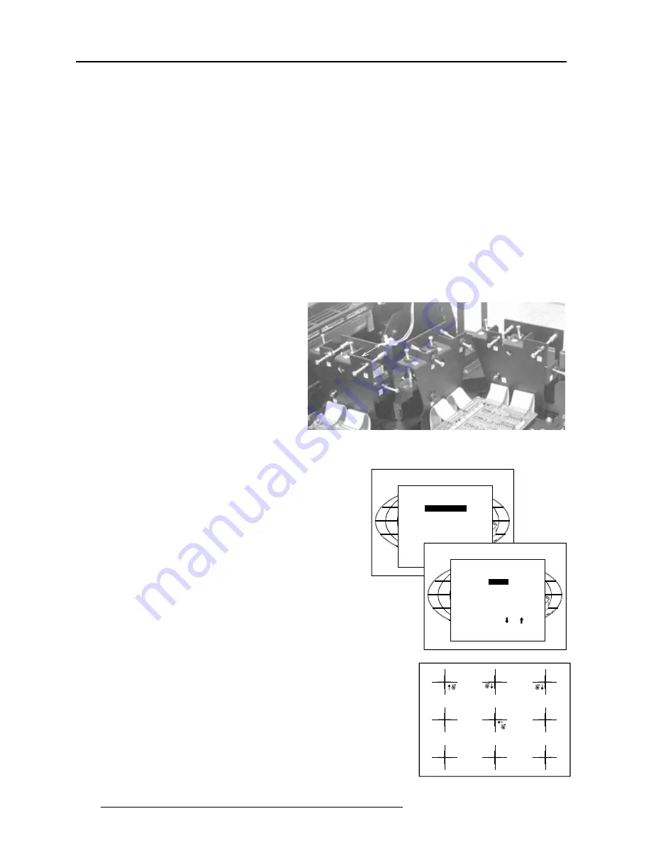
The three mounting parts for the LCD's (two are shown on the drawing

below)  are  located  on  the  black  metal  cover.    The  screws  are

indicated from 1 to 6 for each color.

To adjust the convergence, there are test patterns provided in the

service menu.

Push the control stick forward or backward to hightlight 

Convergence

and press 

ENTER

 to display the 

Convergence

 menu.

Start with the Green test pattern and continue with the Blue on green

and finish with the Red on green.

INSTALLATION

INPUT SLOTS

CONVERGENCE

CONFIGURATION

OSD COLOR

INTERNAL PATTERNS

NO SIGNAL [BLACK]

The pattern shows lines of one pixel.

Near six  lines on the displayed pattern, a screw is drawn with a

number next to it (e.g. if displayed in green = corresponding with the

screws and numbers on the green LCD panel).

When turning a screw in the direction marked by the arrow above the

displayed screw on the screen, the line on the screen moves in the

direction of the straight arrow.

Select with        or

then <ENTER>

<EXIT> to return.

CONVERGENCE

GREEN

BLUE ON GREEN

RED ON GREEN

HATCH

Summary of Contents for BarcoData 3300

Page 1: ...INSTALLATION MANUAL R9001450 DATA 3300 TCRPLUS ...

Page 2: ...BARCO PROJECTION SYSTEMS INSTALLATION MANUAL Date 121097 Art No R5975129 R9001450 DATA 3300 TCRPLUS ...

Page 3: ...equipment does cause interference to radio or television reception the user may try to correct the interference by one or more of the following measures Re orientation of the receiving antenna for the radio or television Relocate the equipment with respect to the receiver Plug the equipment into a different outlet so that the equipment and receiver are on different branch circuits Fasten cables co...

Page 4: ...121098 i TABLE OF CONTENTS TABLEOFCONTENTS i 1 INSTALLATIONMODE 1 1 Starting up the Installation Mode 1 1 Configuration 1 1 Internal Patterns 1 1 How to use the built in adjustable lensholder 1 2 HARDWARESETUP 2 1 How to activate the password function 2 1 ...

Page 5: ...ue screen when no source is connected to the projector Only the items used during the physical installation will be explained hereafter The other items are explained in the owners manual Select with or then ENTER EXIT to return INTERNAL PATTERNS OUTLINE COLOR BARS MULTIBURST CHECKER BOARD PURITY PAGE CHAR ALPHA NUMERIC CHAR GRAY BARS Select with or then ENTER EXIT to return Configuration Highlight...

Page 6: ... to a computer in chapter Connections The three mounting parts for the LCD s two are shown on the drawing below are located on the black metal cover The screws are indicated from 1 to 6 for each color To adjust the convergence there are test patterns provided in the service menu Push the control stick forward or backward to hightlight Convergence and press ENTER to display the Convergence menu Sta...

Page 7: ...ngest lines are the blue lines These lines must be converged with the green lines The drawn screws and numbers are displayed in blue Follow next steps Blue focusing a Insure all convergence screws are adjusted to a length of about 33 mm 1 3 between the two plates b Turn screw 1 for optimal focus of the corresponding point 1 on the screen c Turn screw 2 for optimal focus of the corresponding point ...

Page 8: ...ensholder With the lensholder it is possible to shift the displayed image up or down on the screen without moving the projector from its normal positioin and without any geometric picture distortion This built in feature is particularly useful for use in dual projector configurations or for applications when the projector cannot be installed in its standard position Features Vertical and horizonta...

Page 9: ... Use the hand screw Shift the image up or down until the correct vertical position of the image is obtained Turn clockwise to shift the image up turn counter clockwise to shift down Use the hand screw Midposition of the adjustable lensholder If the top cover is opened the lensholder indication line has to match with the center of the hole in the plate behind the lensholder If the top cover is clos...

Page 10: ...ower down the projector and unplug the power cord from the wall outlet Turn both lock screws with a screwdriver or coin counter clockwise Lift up and pivot the top cover Attention the cover is not secured with an incorporated support When opening turn it over slowly The processor module with the DIP switches is located on the front side Loosen the locking screws Open the top cover When DIP switch ...

Reviews: