


Sensor Setup
Setting the Cutoff Distance
The cutoff distance for the QS18AF models may be adjusted between 20 mm
and 100 mm (0.8 in to 4 in); for QS18LAF models, between 30 mm and 150
mm (1.2 in to 6 in); and for QS18LAF250 models, between 50 mm and 250
mm (2 in to 10 in).
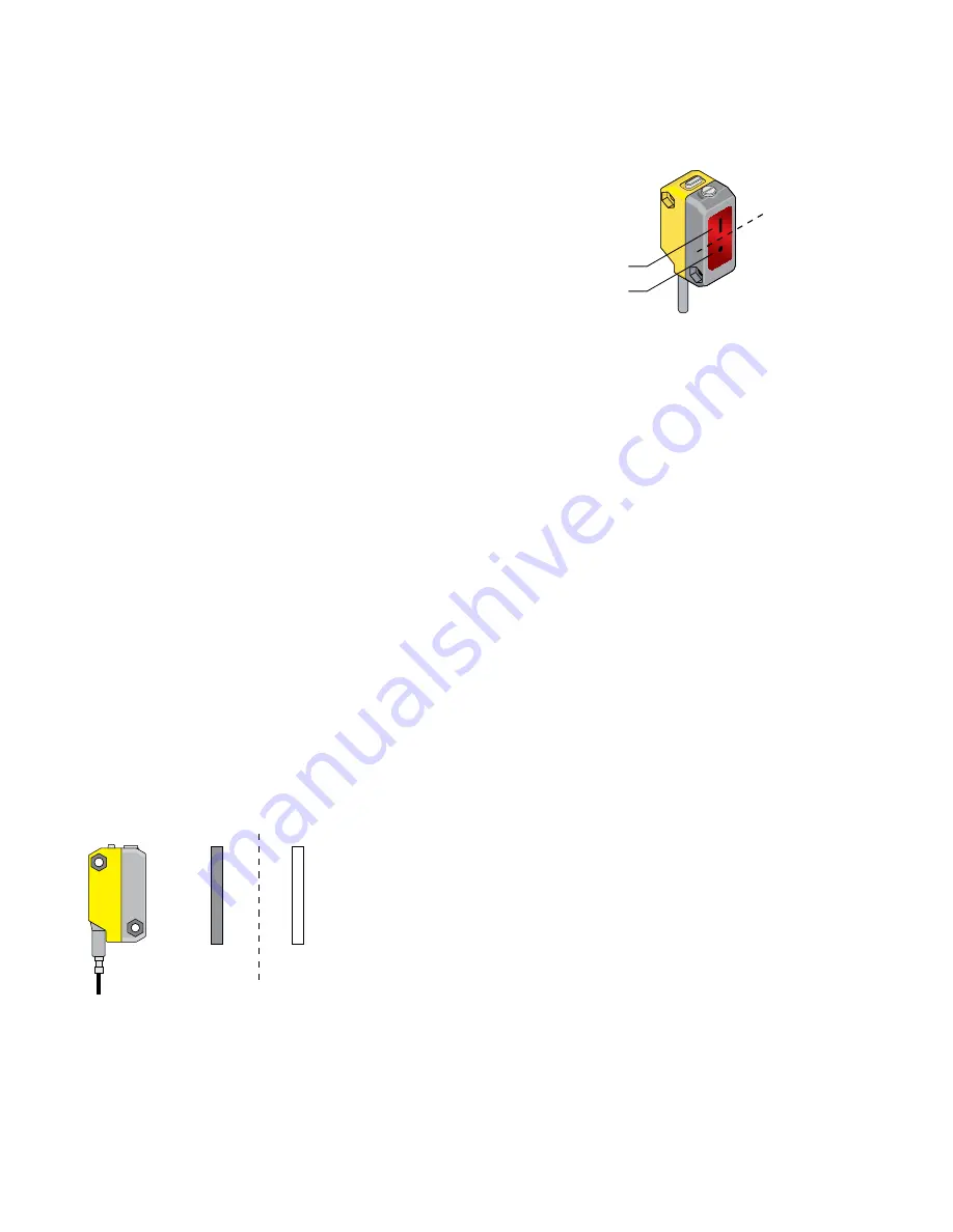
To properly set the cutoff point, position the lightest possible background to
be used, at the closest position it will come to the sensor during use. Using a
small screwdriver in the adjustment screw, adjust the cutoff distance until the
threshold is reached and the yellow Light Sensed indicator changes state. (If
the indicator never comes ON, the background is beyond the maximum sens-
ing distance and will be ignored.) Repeat the procedure, using the darkest
target, placed in its most distant position for sensing. Adjust the cutoff approx-
imately midway between the two positions (
Figure 4. Set cutoff distance ap-
proximately midway between the farthest target and the closest background
on page 3).
Receiver
Elements
Sensing
Axis
Emitter
When an object approaches from the side,
the most reliable sensing usually occurs
when the line of approach is parallel to the
sensing axis.
Figure 3. Sensing Axis
Sensing Reliability
For highest sensitivity, the sensor-to-object distance should be such that the object will be sensed at or near the point of maximum ex-
cess gain. The excess gain curves show excess gain vs. sensing distance for the minimum and maximum cutoff settings. Maximum
excess gain for model QS18VN6AF100 at a 20 mm cutoff occurs at a lens-to-object distance of about 7 mm, for example. The back-
ground must be placed beyond the cutoff distance; more reflective backgrounds should be placed even farther back. Following these two
guidelines will maximize sensing reliability.
Background Reflectivity and Placement
Avoid mirror-like backgrounds that produce specular reflections. False sensor response will occur if a background surface reflects the
sensor’s light more strongly to the near detector (R1) than to the far detector (R2). The result is a false ON condition (
on page 4). Use of a diffusely-reflective (matte) background will cure this problem. Other possible solutions are
Reflective background – solution
on page 4). Position the background as far beyond the cutoff distance as possible.
An object beyond the cutoff distance, either stationary (when positioned as shown in
Figure 7. Object beyond cutoff – problem
4) or if it moves past the face of the sensor in a direction perpendicular to the sensing axis, can cause unwanted triggering of the
sensor if it reflects more light to the near detector than to the far detector. The problem is easily remedied by rotating the sensor 90°
(
Figure 8. Object beyond cutoff – solution
on page 4). The object then reflects the R1 and R2 fields equally, resulting in no false
triggering. A better solution, if possible, may be to reposition the object or the sensor.
E
R2
R1
Target
Background
Cutoff
Distance
Figure 4. Set cutoff distance approximately midway between the farthest target and the closest background
WORLD-BEAM
®
QS18 Adjustable-Field Sensors
P/N 66981_web
Rev. I
www.bannerengineering.com - tel: 763-544-3164
3


