5 Rapid Configuration
5.1 STEP 1 – Connect the System
NOTE: This section illustrates a standalone application. For a pass-through installation, refer to the
appropriate section. For complete scanner configuration using the GeniusPlus configuration program,
refer to the Context-Sensitive Help On-Line.
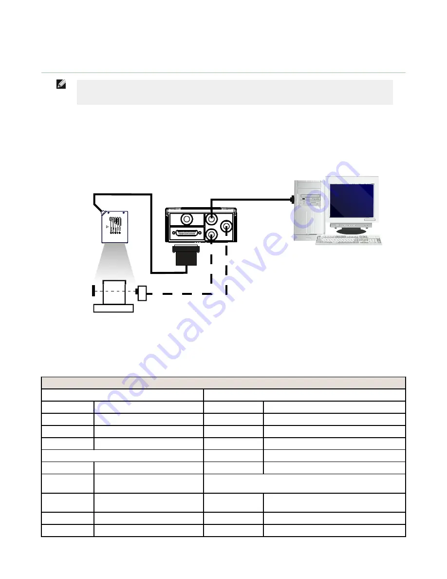
To connect the system in a standalone configuration, you need the hardware indicated below. In this layout, the data is
transmitted to the Host on the main serial interface.
•
In Local Echo communication mode, data is transmitted on the RS-232 auxiliary interface independently from the
main interface selection.
•
When On Line Operating mode is used, the scanner is activated by an External Trigger (photoelectric sensor) when
the object enters its reading zone.
Barcode
Scanner
Host
Trigger
* Presence Sensor
(for On-Line mode)
MAIN
I/O, AUX
TCNM-ACBB1
Figure 8. Barcode scanner in a standalone layout
5.1.1 TCNM-ACBB1 Pinout
The table below gives the pinout of the TCNM-ACBB1 terminal block connectors. Use this pinout when the barcode scanner
is connected using the TCNM-ACBB1:
TCNM-ACBB1 Terminal Block Connectors
Input Power
Outputs
Vdc
Power Supply Input V
+V
Power Source - Outputs
GND
Power Supply Input Voltage –
–V
Power Reference - Outputs
Earth
Protection Earth Ground
O1+
Output 1 +
O1–
Output 1 –
Inputs
O2+
Output 2 +
+V
Power Source – External Trigger
O2-
Output 2 –
I1A
External Trigger A (polarity
insensitive)
Auxiliary Interface
I1B
External Trigger B (polarity
insensitive)
TX
Auxiliary Interface TX
–V
Power Reference – External Trigger
RX
Auxiliary Interface RX
+V
Power Source – Inputs
SGND
Auxiliary Interface Reference
TCNM AD/EX Barcode Scanner
14


