Collocated Radios
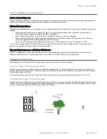
When the radio network’s master device is located too close to another radio device, communications between all devices is
interrupted. For this reason, always assign a unique Network ID to your wireless networks.
The Network ID (NID) is a unique identifier you assign to each wireless network to minimizes the chances of two collocated
networks interfering with each other. Assigning different NIDs to different networks improves collocation performance in dense
installations.
Do not install antennas within the minimum separation distance.
Antenna Minimum Separation Distance
900 MHz, 150 mW and 250 mW: 2 m (6 ft)
900 MHz, 1 Watt: 4.57 m (15 ft)
2.4 GHz, 65 mW: 0.3 m (1 ft)
Be Aware of Seasonal Changes
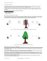
When conducting the initial Site Survey, the fewest possible missed packets for a given link is better. However, seasonal changes
may affect the signal strength and the total signal quality. Radios installed outside with 50% missed packets in the winter months
may have 80% or more missed packets in the summer when leaves and trees interfere with radio reception.
Figure 1. A good signal in winter doesn't always mean you will get the same signal strength the rest of the year.
Figure 2. During spring and summer, leaves may block more of the radio signal.
Basic Remote Antenna Installation
A remote antenna system is any antenna system where the antenna is not connected directly to the radio; coaxial cable connects
the antenna to the radio.
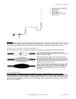
When installing a remote antenna system, always include a lightning arrestor or coaxial surge suppressor in the system. Remote
antenna systems installed without surge protection invalidate the warranty of the radio devices.
Surge suppressors should be properly grounded and mounted at ground level near where the cabling enters a building. Install the
surge suppressor indoors or inside a weatherproof enclosure to minimize corrosion or component deterioration. For best results,
mount the surge suppressor as close to the ground as possible to minimize the length of the ground connection and use a single-
point ground system to avoid creating ground loops.
For more detailed information about how antennas work and how to install them, refer to
(p/n 132113) (also
included as a chapter within the product manual).
Installing Your Sure Cross
®
Radios
P/N 151514 Rev. D
www.bannerengineering.com - Tel: +1-763-544-3164
3


