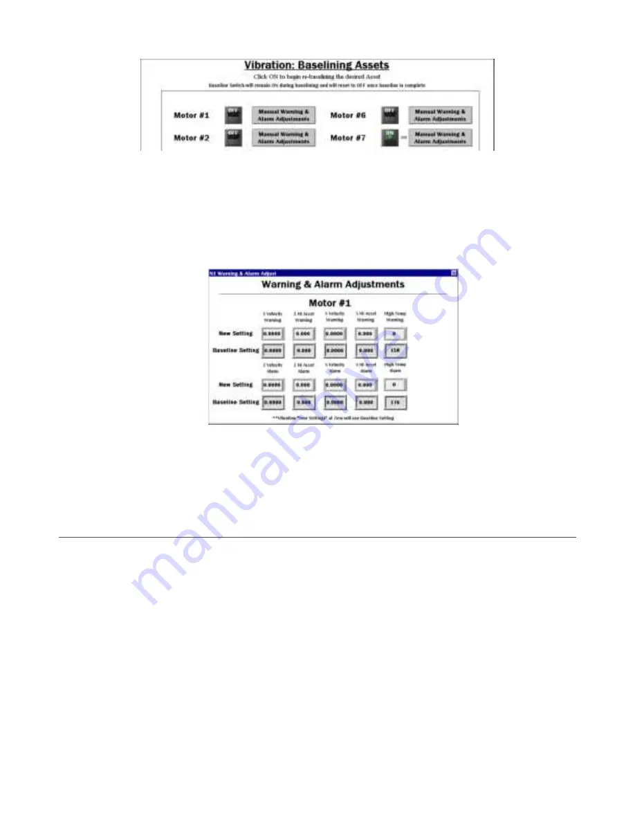
1. Turn on baselining for the appropriate Nodes if a new baseline needs to be generated.
The initial baseline is generated any time a new sensor is connected to the system (or bound to the controller radio) and
begins sending data without the need to trigger these switches. The number of baseline samples remaining displays next to
the ON/OFF switch. The baseline switch remains on during baselining and resets to off after the baseline is complete.
2. Use the tabs Assets #1-10, Assets #11-20, Assets #21-30, and Assets #31-40 to access the baseline switches for the
sensors/radios.
3. Use the corresponding
Manual Warning & Alarm Adjustments
button for each sensor/radio to open an individual
windowed screen where current baseline threshold settings are visible.
4. Touch the numeric entry box in any of the
New Settings
rows to manually enter a new value for any or all the warning or
alarm thresholds, including temperature.
5. Set vibration settings back to zero to use the original baseline setting.
6. Manually set the temperature back to the baseline setting by entering 158 °F (70 °C) for warning or 176 °F (80 °C) for alarm.
Temperature is not a baselined value. Although it displays a baseline value, the value is for reference if the new setting is
changed.
HMI Options Menu Screen
The HMI Options screen provides some added HMI functionality along with icon and graph legends.
The HMI provides data logging of all the raw data, baselines, and thresholds. This data is saved to a file every 30 minutes and a new
file is generated every day and stored in monthly folders. The HMI has storage for about 45 days of log files.
Vibration Monitoring and Predictive Maintenance Solutions Kit Quick Start Guide (MultiHop)
P/N 214301 Rev. F
www.bannerengineering.com - Tel: + 1 888 373 6767
7


