


Distance Settings—Match Distance Settings
Discrete 1
—The distance matches the distance settings of Discrete 1. If Discrete 1 is in Output Mode
Switch Point
,
the sensing window is 0.1 m to Switch Point 1. If Output Mode is
Window
, the sensing window is between Switch
Point 1 and Switch Point 2.
Discrete 2
—The distance matches the distance settings of Discrete 2. If Discrete 2 is in Output Mode
Switch Point
,
the sensing window is 0.1 m to Switch Point 2. If Output Mode is
Window
, the sensing window is between Switch
Point 1 and Switch Point 2. If Output Mode is
Complementary
, the sensing window matches Discrete 1.
Custom
—The sensing window is defined by setting the Near Switch Point and Far Switch point. It is independent of
both Discrete 1 and Discrete 2.
Near Detection
The LED behavior when the object is between the minimum sensing range and Switch Point 1.
Sensing Window
The LED behavior when the object distance is within Switch Point 1 and Switch Point 2. A steady global background
color and intensity can be applied.
Far Detection
The LED behavior when the object is between the maximum sensing range and Switch Point 2.
Loss of Signal
The LED behavior when no object is present, or outside of the sensing range.
6.2 Four State Mode
When using Four State Full Logic, the sensor can be programmed to display LED indication states for up to four sensor
states or zones. The states depend on the discrete output windows set in the
Discrete 1
and
Discrete 2
tabs.
Example applications:
•
Visual indication for warning zones
•
Availability of parking space
•
Product placement or position
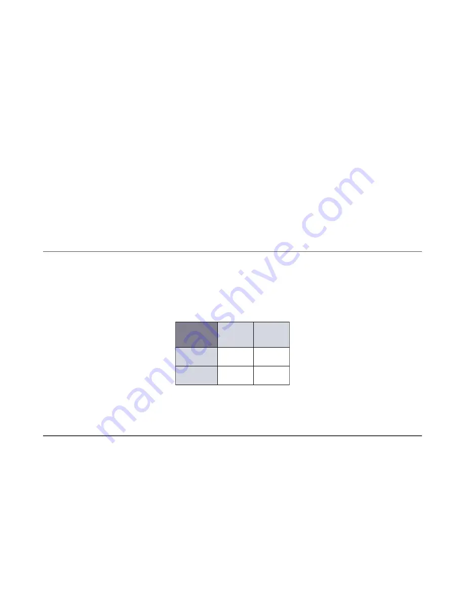
Figure 11. Four State Full Logic Table
State 1
Discrete 2
ON
Discrete 2
OFF
Discrete 1
OFF
Discrete 1
ON
Four State
Full Logic
State 3
State 2
State 4
To select Four State mode, select
Four State
from the
Device Logic
menu on the
Indication
tab.
Use the options to set the sensor animation and color(s) for each logic state.
6.3 Enable/Disable the LEDs
If the LEDs become distracting or to conserve power, they can be disabled.
Use the following procedure to enable or disable the LEDs.
1. On the
Indication
tab, on the
Device Logic
menu, select
LEDs Disabled
.
The option turns yellow.
2. Click
Write
to write the parameter to the sensor.
The LEDs are disabled.
3. To enabled the LEDs, select either
Distance
or
Four State
from the
Device Logic
menu.
4. Click
Write
to write the parameter to the sensor.
The LEDs are enabled and the sensor can be configured for Distance or Four State.
R-GAGE
®
K50R Radar Sensor
www.bannerengineering.com - Tel: + 1 888 373 6767
21


