

Diagnostic Display
8
Error Description
Appropriate Action
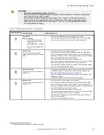
EDM Error
This error can occur when the EDM
input is open at power up or if the signal
fails to respond within 250 ms of the
OSSDs changing state (On to Off).
•
Verify that the EDM wiring is correct and that the external devices meet the
requirements described in
Machine Primary Control Elements and EDM Input
on page 43
•
If the error continues, remove power to the guarded machine, disconnect the
OSSD loads, disconnect the EDM input signals, configure EDM for No
Monitoring (per
Machine Primary Control Elements and EDM Input
on page 43)
and conduct the Initial Checkout procedure
•
If the error clears, the problem is in the External Device contacts or wiring, or is
a response-time problem of the external devices. Verify that the EDM wiring is
correct and that the external devices meet the requirements described in
Machine Primary Control Elements and EDM Input
on page 43
•
If the error continues, check for noise on the EDM inputs (see
on page 60)
9.2.2 Emitter Error Codes
Diagnostic
Display
9
Error Description
Appropriate Action
Emitter Error
This error can occur if the ID Input
(pin 3, Orange) is not connected to
+24 V DC.
Excessive electrical noise or an
internal failure can also cause this
error.
•
Verify that the ID Input (ID_in) wiring is connected to +24 V DC. See
•
Cycle the power to the emitter per
on page 58
•
If the error clears, perform the daily checkout procedure (per EZ-SCREEN
Checkout Procedures: Shift and Daily Checkout Procedure; Daily Checkout Card).
If the System checks out, resume operation. If the System fails, replace the emitter
•
If the error continues, check the ground connection (see
on page 62)
•
If the sensor has a good earth ground connection, check for electrical noise (see
•
If the error persists, replace the emitter
Emitter LED Problem
This is not an error.
This indication can occur due to a potential problem with an LED and is provided as an early
warning indicator
9.3 Electrical and Optical Noise
The EZ-SCREEN LS Basic is designed and manufactured to be highly resistant to electrical and optical noise and to operate
reliably in industrial settings. However, serious electrical and/or optical noise may cause a random Trip. In very extreme
electrical noise cases, a Lockout is possible. To minimize the effects of transitory noise, the EZ-SCREEN LS Basic dual scan
technology responds to noise only if the noise is detected on multiple consecutive scans.
If random nuisance Trips or lockouts occur, check the following:
•
Poor connection between the sensor and earth ground
•
Optical interference from adjacent light screens or other photoelectrics
•
Sensor input or output wires routed too close to noisy wiring
9.3.1 Check for Sources of Electrical Noise
It is important that the light screen sensors have a good earth ground. Without this, the System can act like an antenna and
random Trips and Lockouts can occur.
All EZ-SCREEN LS Basic wiring is low voltage; running these wires alongside power wires, motor/servo wires, or other high-
voltage wiring can inject noise into the EZ-SCREEN LS Basic System. It is good wiring practice (and may be required by
code) to isolate EZ-SCREEN LS Basic wires from high-voltage wires.
1. Use the Banner model BT-1 Beam Tracker Alignment Aid (see
on page 70) to detect electrical
transient spikes and surges.
2. Cover the lens of the BT-1 with electrical tape to block optical light from entering the receiver lens.
3. Press the RCV button on the BT-1 and position the Beam Tracker on the wires going to the EZ-SCREEN LS Basic or
any other nearby wires.
8 Multiple-digit codes are sequential, followed by a pause.
9 Multiple-digit codes are sequential, followed by a pause.
EZ-SCREEN
®
LS Basic Safety Light Curtain
60
www.bannerengineering.com - Tel: + 1 888 373 6767