

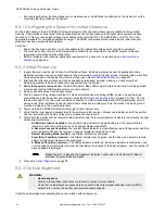

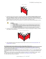

Note:
If at any time the red Status indicator begins to flash steadily, the System has entered a Lockout
condition. See
on page 58 for further information.
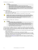
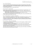
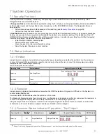
Indicator LEDs
Run Mode Indicator (Off)
Status Indicator (Flashing Red)
Diagnostic Display
(Error Code)
Alignment Indicator (Off)
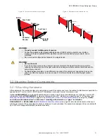
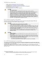
6.3.4 Optical Alignment Procedure with Mirrors
EZ-SCREEN LS Basic sensors may be used with one or more corner mirrors for guarding more than one side of an area.
The MSM-... and SSM-... rear-surface glass mirrors are rated at 85% efficiency. Thus, excess gain and sensing range are
reduced when using mirrors; see
on page 28.
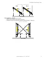
During any adjustments, allow only one individual to adjust any one item at any one time. In addition to the standard optical
alignment procedure, verify:
1. The emitter, receiver, and all mirrors are level and plumb.
2. The middle of the defined area and the center point of the mirrors are approximately the same distance from a
common reference point, such as the same height above a level floor.
3. There are equal amounts of mirror surface above and below the defined area such that the optical beams are not
passing below or above the mirror.
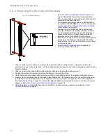
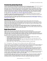
Note:
An LAT-1 Laser Alignment Tool is very helpful by providing a visible red dot along the optical axis.
on page 70,
on page 40, and Banner Safety Applications Note SA104
(p/n
) for more information.
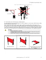
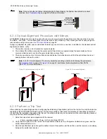
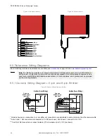
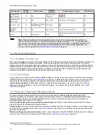
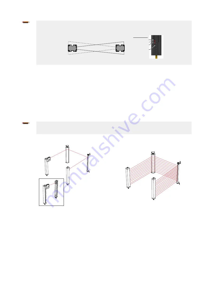
Figure 28. Optical alignment using the LAT-1
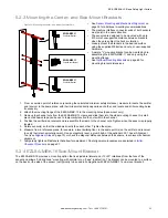
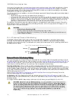
Figure 29. Corner Mirror Alignment
Component 2 (Mirror)
Component 3 (Mirror)
Component 4 (Receiver)
Component 1 (Emitter)
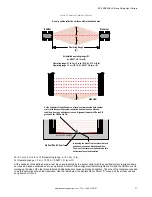
6.3.5 Perform a Trip Test
After optimizing the optical alignment and configuring fixed blanking (if applicable), perform the trip test to verify the detection
capability of the EZ-SCREEN LS Basic System. This test also verifies correct sensor orientation and identifies optical short
circuits. After the installation has passed the trip test, the safety outputs may be connected and the commissioning checkout
may be performed (initial installations only).
1. Select the proper test piece supplied with the receiver.
•
23 mm resolution models: 23 mm (0.91 in) dia. Model STP-19
2. Verify that the System is in Run mode, the Green Status indicator is On, all Alignment indicators are green, and the
amber Status indicator is On.
3. Pass the specified test piece through the defined area in three paths: near the emitter, near the receiver, and midway
between the emitter and receiver.
EZ-SCREEN
®
LS Basic Safety Light Curtain
40
www.bannerengineering.com - Tel: + 1 888 373 6767