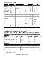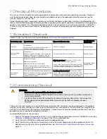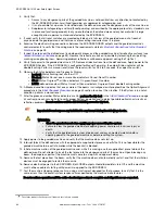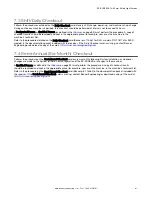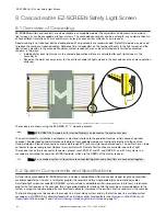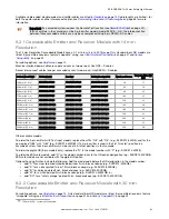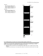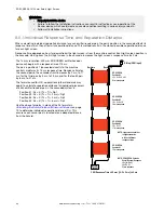
Machine interface/power cables (one per end sensor, two per pair): Use QDE-..D cables.
Sensor interconnect cables (one per cascaded sensor, two per pair): Use DEE2R-..D cables.
Defined Area Height12
Emitter (8-pin)
Receiver
Emitter/Receiver Pair
Number of
Beams
Response Time
(Tr) (ms)
300 mm (11.8 in)
SLSCE30-300Q8
SLSCR30-300Q8
SLSCP30-300Q88
20
11
450 mm (17.7 in)
SLSCE30-450Q8
SLSCR30-450Q8
SLSCP30-450Q88
30
13
600 mm (23.6 in)
SLSCE30-600Q8
SLSCR30-600Q8
SLSCP30-600Q88
40
15
750 mm (29.5 in)
SLSCE30-750Q8
SLSCR30-750Q8
SLSCP30-750Q88
50
17
900 mm (35.4 in)
SLSCE30-900Q8
SLSCR30-900Q8
SLSCP30-900Q88
60
19
1050 mm (41.3 in)
SLSCE30-1050Q8
SLSCR30-1050Q8
SLSCP30-1050Q88
70
21
1200 mm (47.2 in)
SLSCE30-1200Q8
SLSCR30-1200Q8
SLSCP30-1200Q88
80
23
1350 mm (53.1 in)
SLSCE30-1350Q8
SLSCR30-1350Q8
SLSCP30-1350Q88
90
25
1500 mm (59 in)
SLSCE30-1500Q8
SLSCR30-1500Q8
SLSCP30-1500Q88
100
27
1650 mm (65 in)
SLSCE30-1650Q8
SLSCR30-1650Q8
SLSCP30-1650Q88
110
30
1800 mm (70.9 in)
SLSCE30-1800Q8
SLSCR30-1800Q8
SLSCP30-1800Q88
120
32
1950 mm (76.8 in)
SLSCE30-1950Q8
SLSCR30-1950Q8
SLSCP30-1950Q88
130
32
2100 mm (82.7 in)
SLSCE30-2100Q8
SLSCR30-2100Q8
SLSCP30-2100Q88
140
36
2250 mm (88.6 in)
SLSCE30-2250Q8
SLSCR30-2250Q8
SLSCP30-2250Q88
150
38
2400 mm (94.5 in)
SLSCE30-2400Q8
SLSCR30-2400Q8
SLSCP30-2400Q88
160
40
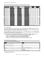
Other available models:
To order the 5-pin emitters with the Test input, replace suffix “Q8” with “Q5”, (e.g., SLSCE30-300Q5), and for the pair
replace “Q88” with “Q85” (e.g., SLSCP30-300Q85). If a 5-pin emitter is used in the first (“master”) position in a cascaded
system, then 5-pin emitters must be used in all other positions in that cascade.
To order the pigtail QD (8-pin models only) model, replace the “Q” in the model number with “P” (e.g., SLSCE30-300P8).
To order the ESD-safe models, add “N” to the model number, prior to the QD option designation (e.g., SLSCE30-300NQ8).
ESD-safe models are not available with the pigtail QD option.
Optional housing finishes include the following. Add the model code before the QD designation in the model number:
• add “A” for a clear (brushed) anodized aluminum finish, black endcaps (e.g., SLSCE30-300AQ8),
• add “S” for a nickel-plated (“silver”) finish, black endcaps (e.g., SLSCE30-300SQ8),
• add “B” for a black painted finish, black endcaps (e.g., SLSCE30-300BQ8),
• add “W” for a white painted finish, black endcaps (e.g., SLSCE30-300WQ8), or
• add “SO” for a “safety orange” painted finish, black endcaps (e.g., SLSCE30-300SOQ8).
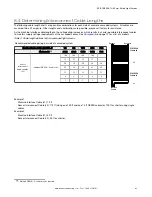
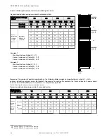
8.3 Receiver Display
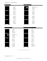
In Run mode, the 7-digit display shows the following.
Condition
Display
Clear Condition—Latch output operation
Clear Condition—Trip output operation
Blocked
Number of blocked beams (sequential)
CSSI Input Off or open, for example, “upstream” receiver is blocked or in
lockout
Solid (not flashing)
12 150 mm SLSC.. systems not available.
EZ-SCREEN
®
14/30 mm Safety Light Screen
64
www.bannerengineering.com - Tel: + 1 888 373 6767

