

Basic Configuration
Master mode STM32F303CB, inner parameter 32bit/72MHz/256k Flash/40k SRAM
MPU6050 sensors
Build-in 8MB flash
Support PPM/SBUS/SumD/DSM2/DSMX and RSSI signal input
On board OSD with MAX7456EUI and FTDI
Connectors for SWD/GPS/MAG/soft-serial/cam-stab servo
On board Buzzer 12WS28128B RGB colorful LED and 5V-3A BEC
On board Voltage sensors
20A ESC 3-4S with BLHeli firmware
High power MR2205/2550KV motors and 5 inch propellers
1/3'' CMOS lens
200 mW video transmitter, 32 channels to choose
Disconnect power, USB cable and OSD
Click load firmware[local] and found that firmware file/
Be sure selected no reboot sequence/ full chips erase/ manual baud rate25600
Connect shortly flight controller(F3)to upgrade by reserved solder pad
Connect USB cable
Click flash firmware and wait for the prompts to complete it
Released short cable when finishing firmware upgraded
Don't connect any power to the quad
Install FT232VCP driver and connect FTDI to UART1(SH) port
Download MWOSD GUI zip file and open it.
http://www.dys.hk/ProductShow.asp?ID=171
Select correct COM port, and wait for reading OSD configuration parameter
Modify the parameter, font and write back to OSD MCU after finishing reading.
The 328P of OSD connected to F3030(F3) via UART1
The GPS connected to F303(F3) via UART2
Extended I2C equipment (such as bluetooth) connected to F303(F3) via I2C
Receiver SBUS signal connected to F303(F3) via UART3
OSD circuit will keep working and communicate with F303(F3) when using battery power supply.
If you plug a USB cable, OSD circuit will be cut off powered to ensure that flight
controller(F3) can communicate with computer.
When debegging OSD, do not connect battery and plug FTDI tool, discoonnect OSD to flight
controller.
At this time, OSD circuit can work independently.
Firmware Flash (Upgraded)
OSD Debug
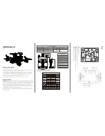
Jack and Power Distribution
Calibrate sensors
Configures ports: Default setting: UART2 used for GPS and UART3 used for serial RX(SBUS)
Enable features: We recommend that you enable ONESHOT125
Configures receiver mode: Default setting: SBUS (RX_serial)
Configures voltage monitoring: voltage scale must be 110
Configures RSSI if you are using a receiver with RSSI output
Configures other features: You can open SERVO-TILT if you connect Cam-stab servo to the frame.
Default settig: LED_Trips / BLACKBOX
Configures receiver: Set channels mapping
Learn about flight modes and configure channels / switches to active them as required
Learn how to arm/disarm
Bench-test failsafe
Read safety notes
Learn how to download and review your flight logs to help to tune your aircraft.
Erase dataflash contents before first flight(so you have a log)
Learn how to recognize un-tuned flight characteristics and effects of PID controllers
(watch some videos)
Basic operation
Appendix
Install latest Silon Labs CP2102 USB to UART bridge VCP driver
http://www.silabs.com/products/mcu/pages/usbtouartbridgevcpdrivers.aspx
Launch the Cleanflight Configurator tool.
https://chrome.google.com/webstore/detail/cleanflight-configurator/
enacoimjcgeinfnnnpajinjgmkahmfgb
Connect flight controller to computer via USB cable, select the correct COM port if it is not
automatically detected.
Click connect, vertify that communication is established
Preparation before Flight
First
First flight should be Acro/Rate modes (the default mode when no other modes are active)
Tune PIDs
Backup settings
Bottom
CAN RSSI LED
BB
UART3
USB
UART2
UA
R
T2
LED
及
RSSI
UA
RT
3
RX
TX
5V
G
N
D
BU
ZZ
LE
D
SK
IP
RSSI
C
A
N
T
C
H
8IN
C
H
7IN
5V
G
N
D
RX
TX
5V
G
N
D
UART3:
SBUS receiver input port
UART2:
GPS
8pin input port:
CH7 and CH8 are double input,
can be used communication signal
input for 7 and 8, also can be used
ultrasonic input.
LED SKIP:
Colorful LED signal output