background image

6

This chapter describes how to 

connect BeoVision 4 to a Bang &

Olufsen BeoSystem 1.

Please refer to the facing page for

more information about the socket

panels on BeoVision 4.

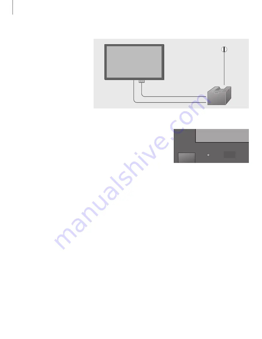
Connect BeoVision 4 to BeoSystem 1

Connect cables and the IR receiver

Make sure that both BeoVision 4 and

BeoSystem 1 are placed properly before 

connecting the systems.

If longer cables are necessary, they are 

available from your Bang & Olufsen retailer.

The plugs at the ends of these cables are all 

different, so it is not possible to connect the

cables incorrectly if you follow the procedure

described below:

> Connect the appropriate plug end of the first

cable to the PROJ. OUT socket on BeoSystem 1,

and the plug group at the other end to the

COMPONENT/RGB-IN sockets on BeoVision 4.

The plugs at the screen end are colour-coded as

follows:

Red… connect to the Pr/Cr/R socket.

Blue… connect to the Pb/Cb/B socket.

Green… connect to the Y/G socket.

Black (or yellow)… connect to the VD socket.

Grey (or white)… connect to the HD socket.

> Connect one end of the second cable to the

DATA socket on BeoSystem 1, and the other

end to the SERIAL socket on BeoVision 4.

> Connect the IR receiver to BeoSystem 1 as 

described in the BeoSystem 1 Guide in the

chapter 

Connect the IR receiver

.

PROJ. OUT

DATA

SERIAL

COMPONENT
RGB
IN

IR RECEIVER

ON / STAND BY

When connections are complete…

> Connect BeoVision 4 to the mains using the

enclosed mains cable.

> Connect BeoSystem 1 to the mains as described

in the BeoSystem 1 Guide.

> Press the mains switch on the BeoVision 4

close-up operation panel. The indicator light

next to the switch turns green. BeoVision 4 is

ready for use with BeoSystem 1. You can now

tune TV channels in, as described in the

BeoSystem 1 Guide.

Summary of Contents for BeoVision 4

Page 1: ...1 BeoVision 4 Guide...

Page 2: ...less the blades can be fully inserted to prevent blade exposure Complete all the connections in your setup before connecting any appliance to the AC outlet Note Your BeoVision 4 operates on a 120 volt...

Page 3: ...e stand or bracket for instruction Contents of the Guide Set up BeoVision 4 4 Handling BeoVision 4 4 Placing BeoVision 4 in your home 5 Overview of the close up operation and socket panels 5 Running t...

Page 4: ...ision 4 can not be tipped over or jostled loose from the selected bracket or stand Set up place and connect BeoVision 4 in accordance with this Guide BeoVision 4 is developed for indoor use in dry dom...

Page 5: ...sound distortion Do not place any items on top of BeoVision 4 Do not place or use BeoVision 4 near water e g near a bathtub sink or swimming pool Do not cover the ventilation holes e g by placing Beo...

Page 6: ...ision 4 The plugs at the screen end are colour coded as follows Red connect to the Pr Cr R socket Blue connect to the Pb Cb B socket Green connect to the Y G socket Black or yellow connect to the VD s...

Page 7: ...ection of compatible equipment please contact your Bang Olufsen retailer L AUDIO VIDEO VD HD Pr Cr R Pb Ca B Y G AUDIO AV IN COMPONENT RGB IN PC IN TUNER IN SERIAL S VIDEO L L AUDIO L The rear connect...

Page 8: ...ision 4 on or off The close up operation panel ON STAND BY Buttons on the close up operation panel ON STAND BY Switches the screen on or off The additional buttons on the close up operation panel are...

Page 9: ...etely dry Guidelines for day to day use Do not allow still pictures to be displayed on the screen for an extended period of time as this can cause a permanent after image to remain on the screen Examp...

Page 10: ...le to operate Therefore we hope that you will take the time to tell us about your experiences with your Bang Olufsen product Anything which you consider important positive or negative may help us in o...

Page 11: ...erference will not occur in a particular installation If this equipment does cause harmful interference to radio or television reception which can be determined by turning the equipment off and on the...

Page 12: ...12...

Reviews: