background image

BeoSound 1 

Type 2581, 2582, 2583, 2584, 2585, 2586, 2587, 2590

On-site service guide
English, German, French, Italian, Spanish, Danish, Dutch, Japanese

This On-site service guide must be 
returned with the defective parts/
back-up suitcase !

Summary of Contents for beosound 1 2581

Page 1: ...ype 2581 2582 2583 2584 2585 2586 2587 2590 On site service guide English German French Italian Spanish Danish Dutch Japanese This On site service guide must be returned with the defective parts back...

Page 2: ...d hold STORE Press u VOLUME r to adjust the display light up or down Make and delete Stop Timer Press STOP The minutes is displayed Press STOP to change the number of minutes Wait 5 seconds and the St...

Page 3: ...16 1 Replacement of Antenna loader and speaker units 17 1 Replacement of CD loader and PCB90 CD Mechanism 18 1 Back up suitcase 19 1 Survey of modules Survey of symbols Push with finger in arrow dire...

Page 4: ...cing the defect module This may be either the Main PCB the Switch Mode Power Supply SMPS or one of the other PCBs A complete survey of modules is placed in the back of the guide Before throubleshootin...

Page 5: ...to look through the fault flow chart again to make sure that the conclusion is correct Make the replacement and then check if the fault has been corrected If not the fault flow chart should be able t...

Page 6: ...in wire from 1P600 to 3P1 OK System functionality IR Try with a new Beo4 OK Replace PCB3 OK Replace PCB1 OK Bring BS1 to workshop for repair Replace batteries or Beo4 Keyboard Disfunction of both left...

Page 7: ...K Bring BS1 to workshop for repair Replace Antenna loader Sound No sound in all speakers Replace PCB1 OK Replace PCB2 OK Bring BS1 to workshop for repair No sound in one speaker Unplug 1P500 and measu...

Page 8: ...BS1 to workshop for repair CD No load of CD Measure 1P700pin1 to pin2 5V DC when load 3 Measure 1P5pin12 to pin10 16V DC 2 Replace PCB2 OK Replace the CD loader OK Replace PCB1 OK Bring BS1 to worksh...

Page 9: ...holding it and then from DELETE to RADIO DELETE is 0 and RADIO is 9 Other digits are those in between Next digit just press AERIAL then DELETE RADIO When reading the display in TM please note that al...

Page 10: ...order due to the fact that BeoSound 1 is prepared for theft protection Ensure that PCB2 SMPS is working correctly replace it if necessary Either PCB1 Main PCB or PCB3 Display IR receiver must be repla...

Page 11: ...5 5 2586 7 2587 8 2590 3 No 1 000 No 2 175 FM start Type 2584 152 No 3 216 FM stop Type 2584 180 No 4 0XX XX is variant Type 2583 2590 75 others 50 No 5 000 N0 6 000 No 7 000 No 8 000 No 9 000 Turn of...

Page 12: ...plug nor the metal parts while performing the test as it may influence the measurement Connect mains voltage to BeoSound 1 Reconnect mains voltage and turn on BeoSound 1 See 4 Theft protection if nece...

Page 13: ...des Antennen Laders und der Lautsprechereinheiten 17 1 Austausch des CD Laders und der PCB90 CD Mechanismus 18 1 Reparaturkoffer 19 1 Modul bersicht Symbol bersicht Mit Finger in Pfeilrichtung dr cken...

Page 14: ...Austausch defekter Module Dies kann entweder die Haupt PCB das Schaltnetzteil SMPS oder eine der anderen PCBs sein Eine vollst ndige Modul bersicht befindet sich im hinteren Teil der Anleitung Lassen...

Page 15: ...as Fehlersuchdiagramm erneut durchzugehen um sicherzustellen dass die Fehlerdiagnose richtig ist Nehmen Sie den Modulaustausch vor und pr fen Sie ob der Fehler beseitigt ist Andernfalls sollte das Feh...

Page 16: ...austauschen OK Systemfunktion IR Versuch mit neuer Beo4 OK PCB3 austauschen OK PCB1 austauschen OK BS1 zur Reparatur in die Werkstatt bringen Batterien oder Beo4 austauschen Tastatur Fehlfunktion der...

Page 17: ...ie Werkstatt bringen Antennen Lader austauschen Tonwiedergabe Alle Lautsprecher stumm PCB1 austauschen OK PCB2 austauschen OK BS1 zur Reparatur in die Werkstatt bringen Ein Lautsprecher stumm 1P500 ab...

Page 18: ...erkstatt bringen CD CD wird nicht geladen 1P700Pin1 gegen Pin2 messen 5V DC beim Laden 3 1P5Pin12 gegen Pin10 messen 16V DC 2 PCB2 austauschen OK CD Lader austauschen OK PCB1 austauschen OK BS1 zur Re...

Page 19: ...Sie AERIAL ohne die Taste zu halten und dann von DELETE zu RADIO DELETE ist 0 und RADIO ist 9 Die weiteren Nummern liegen dazwischen F r die n chste Nummer einfach AERIAL dann DELETE RADIO dr cken Bea...

Page 20: ...da das BeoSound 1 f r Diebstahlsicherung vorbereitet ist Sicherstellen dass PCB2 SMPS korrekt funktioniert ggf austauschen Entweder PCB1 Haupt PCB oder PCB3 Display IR Empf nger muss ausgetauscht wer...

Page 21: ...e des BeoSound 1 Siehe 7 2581 1 2582 2 2583 3 2584 4 2585 5 2586 7 2587 8 2590 3 Nr 1 000 Nr 2 175 FM Start Typ 2584 152 Nr 3 216 FM Stopp Typ 2584 180 Nr 4 0XX XX ist die Variante Typ 2583 2590 75 an...

Page 22: ...die Messung beeinflussen kann Anschluss der Netzspannung an das BeoSound 1 Schlie en Sie die Netzspannung wieder an und schalten Sie das BeoSound 1 ein Siehe ggf Abschnitt 4 Diebstahlsicherung Auslese...

Page 23: ...argeur CD et PCB90 m canisme CD 18 1 Valise de maintenance 19 1 Pr sentation des modules Pr sentation des symboles Poussez d un doigt dans le sens de la fl che D brancher la prise interne Brancher la...

Page 24: ...u BeoSound 1 est effectu e en rempla ant le module d fectueux Il peut s agir de la PCB principale de l alimentation en mode commutation SMPS ou de l une des autres PCB Un relev complet des modules fig...

Page 25: ...u l algorithme des d fauts pour s assurer que la conclusion tir e est correcte Effectuer le remplacement puis v rifier si le d faut a t corrig Si non l algorithme des d fauts devrait pouvoir fournir u...

Page 26: ...tionnalit syst me IR Essai avec une nouvelle Beo4 OK Remplacer PCB3 OK Remplacer PCB1 OK Apporter le BS1 l atelier pour r paration Remplacer les piles ou la Beo4 Clavier Mauvais fonctionnement des pav...

Page 27: ...BS1 l atelier pour r paration Remplacer chargeur antenne Son Aucun son dans toutes les enceintes Remplacer PCB1 OK Remplacer PCB2 OK Apporter le BS1 l atelier pour r paration Aucun son dans une encein...

Page 28: ...pour r paration CD Aucun chargement de CD Mesurer 1P700broche1 broche2 5V CC quand charg 3 Mesurer 1P5broche12 broche10 16V CC 2 Remplacer PCB2 OK Remplacer le chargeur de CD OK Remplacer PCB1 OK Appo...

Page 29: ...is appuyer de DELETE RADIO DELETE correspond 0 et RADIO 9 Les autres chiffres sont ceux situ s entre les deux Chiffre suivant il suffit d appuyer sur AERIAL puis DELETE RADIO En lisant l afficheur en...

Page 30: ...d une protection antivol S assurer que la PCB2 SMPS fonctionne correctement la remplacer en cas de besoin Il faut remplacer soit la PCB1 PCB principale soit la PCB3 afficheur r cepteur IR et le BeoSo...

Page 31: ...2586 7 2587 8 2590 3 N 1 000 N 2 175 D but FM Type 2584 152 N 3 216 Fin FM Type 2584 180 N 4 0XX XX est une variante Type 2583 2590 75 autres 50 N 5 000 N 6 000 N 7 000 N 8 000 N 9 000 Eteindre le Be...

Page 32: ...qu il pourrait avoir une influence sur les mesures Connecter la tension secteur au BeoSound 1 Remettre la tension secteur et allumer le BeoSound 1 Voir 4 Protection antivol si n cessaire Afficher et...

Page 33: ...mento antenna e degli altoparlanti 17 1 Sostituzione del caricatore per CD e della scheda PCB90 meccanismo per CD 18 1 Borsa di supporto 19 1 Riepilogo dei moduli Riepilogo dei simboli Premere con il...

Page 34: ...oso Potrebbe trattarsi o della PCB principale o dello Switch Mode Power Supply SMPS o di una delle tre schede PCB Un riepilogo completo dei moduli si trova in fondo alla guida Prima di iniziare la rip...

Page 35: ...ei difetti per accertarsi che la conclusione sia corretta Effettuare la sostituzione e controllare quindi che il difetto sia stato eliminato Se non questo il caso il diagramma dei difetti dovrebbe ess...

Page 36: ...3P1 OK Funzionamento del sistema IR Provare con Beo4 nuovo OK Sostituire PCB3 OK Sostituire PCB1 OK Portare a riparare BS1 Sostituire batterie o Beo4 Tastiera Difettosit set tastiera sinistra e destra...

Page 37: ...ituire caricatore antenna Suono Nessun suono proveniente dagli altoparlanti Sostituire PCB1 OK Sostituire PCB2 OK Portare a riparare BS1 Nessun suono in un altoparlante Scollegare 1P500 e misurare l a...

Page 38: ...arare BS1 CD Mancato caricamento CD Misurare 1P700pin1 su pin2 5V DC quando carica 3 Misurare 1P5pin12 su pin10 16V DC 2 Sostituire PCB2 OK Sostituire il caricatore per CD OK Sostituire PCB1 OK Portar...

Page 39: ...E a RADIO DELETE corrisponde a 0 e RADIO 9 Gli altri numeri si trovano fra i due Per il numero successivo sufficiente premere AERIAL seguito da DELETE RADIO Durante la lettura del display in modalit T...

Page 40: ...tto da furto Verificare che PCB2 SMPS funzioni correttamente e sostituire se necessario Nel caso in cui debba essere sostituita o la scheda PCB1 PCB principale o la scheda PCB3 Display ricevitore IR e...

Page 41: ...o Tipo 2584 152 N 3 216 FM arresto Tipo 2584 180 N 4 0XX XX variabile Tipo 2583 2590 75 altri 50 N 5 000 N 6 000 N 7 000 N 8 000 N 9 000 Spegnere il BeoSound 1 Si ricordi di seguire le istruzioni forn...

Page 42: ...egamento del BeoSound1 alla sorgente di alimentazione principale Collegare nuovamente l apparecchio alla sorgente di alimentazione principale ed accendere il BeoSound 1 Vedere 4 Protezione antifurto s...

Page 43: ...as unidades de altavoces 17 1 Sustituci n cargador de CD y de PCB90 Mecanismo de CD 18 1 Maleta de m dulos 19 1 An lisis de los m dulos Significado de los s mbolos Pulsar con el dedo en la direcci n d...

Page 44: ...l m dulo defectuoso Este puede ser el PCB Principal la Fuente de alimentaci n con selector de modalidad SMPS o uno de los otros PCBs Un an lisis completo de los m dulos se encuentra en la parte poster...

Page 45: ...de flujo de fallos para cerciorarse de que la conclusi n es correcta Realice el sustituci n y luego verifique que se haya corregido el fallo Si no es el caso el diagrama de flujo de fallos debe poder...

Page 46: ...a 3P1 OK Funcionalidad del sistema IR Pruebe con un nuevo Beo4 OK Reemplace PCB3 OK Reemplace PCB1 OK Lleve el BS1 al taller para reparaci n Reemplace las bater as o el Beo4 Teclado Mal funcionamient...

Page 47: ...eve el BS1 al taller para reparaci n Reemplace Antena cargador Sonido No hay sonido en ning n altavoz Reemplace PCB1 OK Reemplace PCB2 OK Lleve el BS1 al taller para reparaci n No hay sonido en un alt...

Page 48: ...ara reparaci n CD No se carga el CD Mida 1P700patilla1 a patilla2 5V CC al cargar 3 Mida 1P5patilla12 a patilla10 16V CC 2 Reemplace PCB2 OK Reemplace el cargador de CDs OK Reemplace PCB1 OK Lleve el...

Page 49: ...gitos son los que est n entre estos Para el siguiente d gito simplemente pulse AERIAL y luego DELETE RADIO Cuando se lee la pantalla en el TM observe que tambi n se utilizan figuras HEX A F An lisis...

Page 50: ...t preparado para una protecci n contra robo Cerci rese de que el PCB2 SMPS est funcionando correctamente si fuere necesario reempl celo Se tiene que sustituir el PCB1 PCB Principal o el PCB3 Pantalla...

Page 51: ...3 No 1 000 No 2 175 FM inicio Tipo 2584 152 No 3 216 FM parada Tipo 2584 180 No 4 0XX XX es una variante Tipo 2583 2590 75 otros 50 No 5 000 N0 6 000 No 7 000 No 8 000 No 9 000 Apague el BeoSound 1 R...

Page 52: ...puede influir en la medici n Conecte el BeoSound 1 a la red el ctrica Vuelva a conectar a la red el ctrica y encienda el BeoSound 1 Ver el 4 Protecci n contra robo si fuere necesario Lea y borre los...

Page 53: ...16 1 Udskiftning af antenneloader og h jttalerenheder 17 1 Udskiftning af CD loader og PCB90 CD mekanisme 18 1 Back up kuffert 19 1 Oversigt over moduler Oversigt over symboler Skub med fingeren i pil...

Page 54: ...modul Det kan enten v re hoved PCB et Switch Mode Power Supply SMPS eller et andet PCB Bagest i guiden finder du en komplet oversigt over modulerne F r fejlfinding udf res skal du hvis det er muligt...

Page 55: ...at gennemg fejltr et igen for at sikre at konklusionen er korrekt Foretag udskiftningen og kontroller derefter om fejlen er blevet udbedret Hvis ikke skal fejltr et indeholde et andet forslag til hvad...

Page 56: ...dning fra 1P600 to 3P1 OK Systemfunktionalitet IR Pr v med en ny Beo4 OK Udskift PCB3 OK Udskift PCB1 OK Indlev r BS1 p v rkstedet for reparation Udskift batterier eller Beo4 Tastatur Fungerer b de ve...

Page 57: ...lev r BS1 p v rkstedet for reparation Udskift antenneholder Lyd Ingen lyd i nogen af h jttalerne Udskift PCB1 OK Udskift PCB2 OK Indlev r BS1 p v rkstedet for reparation Ingen lyd fra n af h jttalerne...

Page 58: ...1 p v rkstedet for reparation CD Ingen is tning af CD M l 1P700ben1 til ben2 5V DC n r isat 3 M l 1P5ben12 til ben10 16V DC 2 Udskift PCB2 OK Udskift CD holder OK Udskift PCB1 OK Indlev r BS1 p v rkst...

Page 59: ...fra DELETE til RADIO DELETE er 0 og RADIO er 9 Andre cifre ligger derimellem For at g til n ste ciffer skal du blot trykke p AERIAL og derefter p DELETE RADIO N r du afl ser displayet i TM s bem rk at...

Page 60: ...t for tyverisikring S rg for at PCB2 SMPS virker udskift om n dvendigt Enten PCB1 hoved PCB eller PCB3 display og IR modtager skal udskiftes og der skal t ndes for BeoSound 1 og tyverisikringen aktive...

Page 61: ...2582 2 2583 3 2584 4 2585 5 2586 7 2587 8 2590 3 Nr 1 000 Nr 2 175 FM start Type 2584 152 Nr 3 216 FM stop Type 2584 180 Nr 4 0XX XX er en variant Type 2583 2590 75 andre 50 Nr 5 000 Nr 6 000 Nr 7 000...

Page 62: ...virke m lingen Slut netsp ndingen til BeoSound 1 Slut igen netsp ndingen til og t nd for BeoSound 1 Se om n dvendigt 4 Tyverisikring Udl s og slet fejlkoder Aktiver TM27 og udl s fejlene til serviceb...

Page 63: ...rekereenheden vervangen 17 1 Cd lader en PCB90 cd mechanisme vervangen 18 1 Backup koffertje 19 1 Overzicht van de modules Overzicht van de symbolen Duw met vinger in richting van de pijl Interne stek...

Page 64: ...plaats door vervanging van de defecte module Dit kan de hoofdprintplaat zijn de Switch Mode Power Supply SMPS of een van de andere printplaten Achterin de gids vindt u een compleet overzicht van de m...

Page 65: ...m het foutenstroomdiagram te doorlopen om te controleren of uw conclusie juist is Voer de vervanging uit en controleer vervolgens of de fout is gecorrigeerd Als dat niet het geval is verschaft het fou...

Page 66: ...3P1 OK Systeemfunctionaliteit IR Probeer met een nieuwe Beo4 OK Vervang PCB3 OK Vervang PCB1 OK Breng BS1 naar werkplaats voor reparatie Vervang batterijen of Beo4 Toetsenbord Zowel fout in linker als...

Page 67: ...voor reparatie Vervang antennelader Geluid Geen geluid uit alle luidsprekers Vervang PCB1 OK Vervang PCB2 OK Breng BS1 naar werkplaats voor reparatie Geen geluid uit een luidspreker Ontkoppel 1P500 e...

Page 68: ...werkplaats voor reparatie Cd Cd laadt niet Meet 1P700 pin1 tot pin2 5V DC bij laden 3 Meet 1P5 pin12 tot pin10 16V DC 2 Vervang PCB2 OK Vervang de cd lader OK Vervang PCB1 OK Breng BS1 naar werkplaat...

Page 69: ...n vervolgens op DELETE t m RADIO DELETE is 0 en RADIO is 9 De andere cijfers liggen daar tussenin Voor het volgende cijfer drukt u gewoon op AERIAL en vervolgens op DELETE RADIO Let er bij het aflezen...

Page 70: ...iefstalbeveiliging Controleer of PCB2 SMPS correct functioneert en vervang indien nodig deze module PCB1 hoofdprintplaat of PCB3 schermpje en IR ontvanger moet worden vervangen en de BeoSound 1 moet w...

Page 71: ...582 2 2583 3 2584 4 2585 5 2586 7 2587 8 2590 3 Nr 1 000 Nr 2 175 FM start Type 2584 152 Nr 3 216 FM stop Type 2584 180 Nr 4 0XX XX is variant Type 2583 2590 75 overige 50 Nr 5 000 Nr 6 000 Nr 7 000 N...

Page 72: ...de netstekker als de metalen onderdelen aangezien de meting hierdoor kan worden be nvloed De netspanning aansluiten op de BeoSound 1 Sluit de netspanning opnieuw aan en schakel de BeoSound 1 in Raadpl...

Page 73: ...9 1 1 BeoSound 1 2 3 4 5 BeoSound 1 6 BeoSound 1 10 1 11 1 BeoSound 1 12 1 PCB1 PCB 13 1 PCB 2 SMPS PCB3 IR 14 1 15 1 PCB 4 FM 16 1 17 1 PCB90 CD CD 18 1 19 1 PCB PCB 4 14 1 PCB 4 14 1 PCB 4 PCB...

Page 74: ...1 BeoSound 1 BeoSound 1 X X 10 1 X 4 BeoSound 1 BeoSound 1 PCB SMPS PCB BeoSound 1 1 IR 0 IR CDCD CD CD SBC 444A CD 10 17 19 TM BeoSound 1 10 TM BeoSound 1 TM TM43 3 STATIC ELECTRICITY MAY DESTROY TH...

Page 75: ...9 3 2 4 CD BeoSound 1 1PCB TM27 0 TM2 3 10 20 10 1 X 4 5 BeoSound 1 6 BeoSound 1...

Page 76: ...1P5 2P1pin4 pin12 5V DC 2 PCB2 OK 3P1pin15 3P1pin18 pin11 15V DC 2V DC 4 1P600pin4 1P600pin1 pin18 5V DC 2V DC 1 PCB1 OK BS1 PCB3 OK 1P600 3P1 18pin OK IR Beo4 OK PCB3 OK PCB1 OK BS1 Beo4 OK PCB3 OK P...

Page 77: ...9 5 1P35pin2 pin1 5V DC 2 PCB1 OK BS1 4P154pin2 pin1 5V DC 5 PCB4 OK BS1 PCB1 OK PCB2 OK BS1 1P500 3 10 ohm 3 OK PCB1 OK PCB1 OK OK BS1...

Page 78: ...pin6 8V DC 2 PCB1 OK PCB4 OK PCB4 OK PCB1 OK OK PCB1 OK BS1 BS1 CD CD 1P700pin1 pin2 5V DC 3 1P5pin12 pin10 16V DC 2 PCB2 OK CD OK PCB1 OK BS1 CD 1P2pin2 1P2pin4 pin1 9V DC CD 5V DC 1 PCB1 OK PCB90 OK...

Page 79: ...4 TM Beo4 GO STORE TM AERIAL DELETE RADIO DELETE 0 RADIO 9 AERIAL DELETE RADIO TM HEX A F BeoSound 1 TM 23 TM23 APP OS ra Cd GO TM27 TM27 16 l n GO 4 STOP 0A00 0A80 PCB1 PCB 0B00 0B80 PCB1 PCB 0C01 0C...

Page 80: ...1 BeoSound 1 l 3 11111 BeoSound 1 12 BeoSound 1 PCB1 PCB PCB3 IR PCB2 SMPS PCB1 PCB PCB3 IR BeoSound 1 PCB PCB1 PCB3 Bang Olufsen BeoSound1 l 2 STOP l n STORE STORE DELETE STORE BeoSound1 l 2 STOP l n...

Page 81: ...Sound 1 7 2581 1 2582 2 2583 3 2584 4 2585 5 2586 7 2587 8 2590 3 No 1 000 No 2 175 FM start Type 2584 152 No 3 216 FM stop Type 2584 180 No 4 0XX XX Type 2583 2590 75 50 No 5 000 N0 6 000 No 7 000 No...

Page 82: ...6 BeoSound 1 BeoSound 1 BeoSound 1 Guide BeoSound 1 BeoSound 1 11 1 BeoSound1 AC AC AC 2 AC Ohm A C 1 Mega Ohm or 1 Mega Ohm A C BeoSound 1 BeoSound 1 4 TM27 3 CD CD CD CD SBC 444A CD 10 17 19 BeoSou...

Page 83: ...in1 1P600 pin1 1P35 pin1 1P700 pin1 3P1 pin1 4P154 pin1 2J2 2P1 pin1 1P5 pin1 1P500 pin1 Left Left Right Right Woofer 3 5 2 5 dB 3 2 4 1 5 dB 2 1 4 0 5 dB 1 0 4 0 4 dB 0 0 5 1 4 dB 1 1 5 2 4 dB 2 2 5...

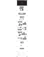
Page 84: ...Disassembly Assembly of BeoSound 1 11 1 Disassembly...

Page 85: ...11 2 Disassembly Assembly of BeoSound 1 Assembly...

Page 86: ...Replacement of PCB1 Main PCB 12 1 CD Loader PCB2 PCB1 CD Loader PCB2 PCB1 CD Loader PCB2 PCB1 1P1 1P500 1P700 1P600 1P2 1P3 1P5 1P35 PCB1 Main PCB...

Page 87: ...13 1 Replacement of PCB2 SMPS and PCB3 Display IR receiver PCB3 Display IR receiver 3P1 3P2 3P3 PCB2 SMPS CD Loader PCB2 PCB1 2P1...

Page 88: ...Replacement of Keyboard Left Right 14 1 Keyboard Left Right 1 2 3 4 3P2 3P3...

Page 89: ...15 1 Replacement of PCB4 Active FM antenna PCB4 Active FM antenna CD Loader PCB2 PCB1 1P5 1P35 14 1 Replacement of Keyboard Left Right 1 3 4P154 4P152 4P151...

Page 90: ...Replacement of Antenna loader and speaker units 16 1 14 1 Replacement of Keyboard Left Right 1 3 Antenna loader 4P154 4P151 4 2 4 Speaker units...

Page 91: ...17 1 Replacement of CD loader and PCB90 CD Mechanism CD loader CD Loader PCB2 PCB1 1P1 1P700 1P2 1P3 13 1 Replacement of PCB3 Display IR receiver 14 1 Replacement of Keyboard Left Right 1 3...

Page 92: ...Replacement of CD loader and PCB90 CD Mechanism 17 2 PCB90 CD Mechanism 17 1 Replacement of CD loader P1000 P1006 P1004 P1000 P1006 P1004...

Page 93: ...ers Also The On site service guide Test CD SBC 444A Bag with wire assortment Bag with screw assortment Screwdriver kit 3 x Torx All parts except Test CD On site service guide and Screwdriver kit are s...

Page 94: ...of modules 19 1 Survey of modules BeoSound 1 PCB1 Main PCB Radio CD LF P PCB2 SMPS Switch mode power supply PCB3 Display IR Receiver PCB4 Active FM antenna PCB90 CD PRO MKII PCB99 CD PRO MKI 1 2 4 3...

Reviews: