BandLuxe
®
M280 Series HSUPA Module Datasheet
23
Section 5
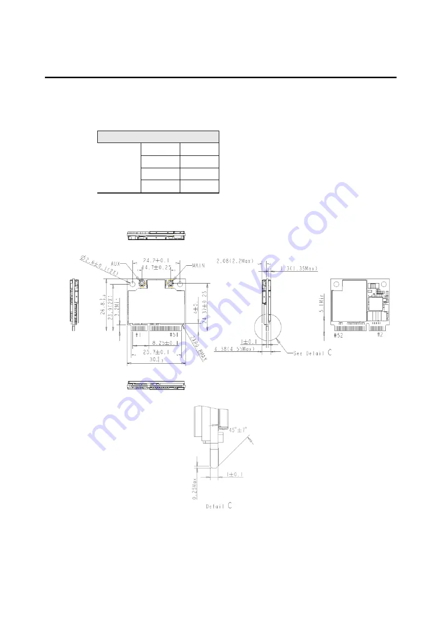
Physical Characteristics
5.1
Dimensions
Table 5-1
M280 Dimensions
Length
26.8 mm
Width
30 mm
Thickness
4.25 mm
Weight
Approx 10 g
Figure 5-1
M280 Dimensioned View
Page 1: ...BandLuxe M280 Series HSUPA Module Datasheet 1 BandLuxe M280 Series HSUPA Module Datasheet 3 3V standard version...
Page 2: ...THER WARRANTY HEREIN ALL DOCUMENT FILES AND SOFTWARE OF THESE SUPPLIERS ARE PROVIDED AS IS WITH ALL FAULTS PRODUCT AND THE ABOVE NAMED SUPPLIERS DISCLAIM ALL WARRANTIES EXPRESSED OR IMPLIED INCLUDING...
Page 3: ...BandLuxe M280 Series HSUPA Module Datasheet 3 Revision History Revision Date Description 1 0 2010 02 25 Draft Document Creation...
Page 4: ...delines and RF Connection 17 2 7 1 Antenna specifications 17 2 7 2 WLAN Antenna Isolation 17 2 7 3 Antenna connector 18 2 8 PCM Interface 18 Section 3 Device Driver Interface 19 Section 4 AT Command S...
Page 5: ...gure 1 2 Bottom View 7 Figure 2 1 M280 Block Diagram 9 Figure 2 2 USB Interface 14 Figure 2 3 USIM Circuits Reference 15 Figure 2 4 System Sleep Mode On Off Level Trigger 16 Figure 2 5 Module Reset 16...
Page 6: ...Operational States 16 Table 5 1 M280 Dimensions 23 Table 5 2 M280 and M280V Electrical Specification 25 Table 5 3 M280 and M280V Recommended Operating Conditions 25 Table 5 4 DC Characteristics Vdd 2...
Page 7: ...Introduction 1 1 General Description The M280 module series is PCI Express Mini Card providing WWAN HSUPA HSDPA WCDMA EGPRS connectivity to laptops or any other device equipped with a PCI Express Min...
Page 8: ...pports GSM voice call via PCM interface 1 2 3 Baseband Functionality The M280 module interfaces with host device through PCI Express Mini Card interface The interface equips with USB2 0 interface USIM...
Page 9: ...BandLuxe M280 Series HSUPA Module Datasheet 9 Section 2 Interface Description 2 1 M280 Block Diagram Figure 2 1 M280 Block Diagram...
Page 10: ...IM_VPP Optional Mechanical Key 17 N C 18 N C 19 WAKEUP Optional 20 W_DISABLE 21 GND 22 PERST 23 N C 24 N C 25 N C 26 GND 27 GND 28 N C 29 GND 30 N C 31 N C 32 N C 33 N C 34 GND 35 GND 36 USB_D 37 GND...
Page 11: ...module to provide status indicators via LED devices that will be provided by the system 42 Communications Specific Signals 2 6V Vdd Compliant W_DISABLE Input Active low level trigger signal This sign...
Page 12: ...t PCM data output for auxiliary codec port 47 PCM_DIN Input PCM data input for auxiliary codec port 49 PCM M280V only PCM_SYNC Output PCM data strobe for auxiliary codec port 51 2 2 3 Power Source and...
Page 13: ...current sink The host drives the device to provide a current path and an appropriate voltage for LED for M280 module Table 2 3 describes the LED output characteristics in different states Table 2 3 LE...
Page 14: ...ar applications The USIM provides the required subscription information to allow the mobile equipment to attach to a GSM or UMTS network The USIM also provides the subscriber s verification procedures...
Page 15: ...w by the module to reactivate the host The M280V module would pull WAKE down for 250ms to send the interrupt to host when it had received a mobile terminated voice call This auxiliary signal interface...
Page 16: ...odule would initiate resuming normal operation when host de asserts the W_DISABLE signal Table 2 5 Radio Operational States W_DISABLE Radio Operation De asserted Enabled RF operation allowed Asserted...
Page 17: ...cies 3dBm Gain for Diversity Antenna 1 Within 3 dB comparing to gain of primary antenna recommended 2 No worse than 6 dB of gain of primary antenna Maximum VSWR 2 5 1 with 50 reference impedance Polar...
Page 18: ...Figure 2 6 Antenna Connector Position and Type Diversity Antenna Connector Main Antenna Connector 2 8 PCM Interface The PCM interface can be used in two modes and supports Linear A Law and Law compoun...
Page 19: ...be modem NDIS interface AT command interface or diagnostics interface All device drivers used by OS have been created for Microsoft Windows 7 Vista 32 64 Windows XP SP2 above Mac OSX and Linux Either...
Page 20: ...BandLuxe M280 Series HSUPA Module Datasheet 20 This page is leave in blank for note or memo use...
Page 21: ...he description of BandLuxe AT Command API please refer to Appendix B for reference For the description of BandLuxe proprietary AT Command API please refer to Appendix C for reference For the call rela...
Page 22: ...BandLuxe M280 Series HSUPA Module Datasheet 22 This page is leave in blank for note or memo use...
Page 23: ...eries HSUPA Module Datasheet 23 Section 5 Physical Characteristics 5 1 Dimensions Table 5 1 M280 Dimensions Length 26 8 mm Width 30 mm Thickness 4 25 mm Dimensions Weight Approx 10 g Figure 5 1 M280 D...
Page 24: ...BandLuxe M280 Series HSUPA Module Datasheet 24...
Page 25: ...heir specified operating ranges Functional operation of the M280 module under any other conditions in Table 5 3 is not implied Table 5 2 M280 and M280V Electrical Specification Parameter Symbol Min Ma...
Page 26: ...0 60 uA Input low leakage current with pull up I_ILPU 60 10 uA High level three state leakage current I_OZH 1 uA Low level three state leakage current I_OZL 1 uA High level three state leakage current...
Page 27: ...x Power Normal Extreme BANDI 3 24 dBm 1 3 dB 1 7 3 7 dB BAND II 3 24 dBm 1 3 dB 1 7 3 7 dB WCDMA BAND V 3 24 dBm 1 3 dB 1 7 3 7 dB 5 3 2 WCDMA Sensitivity Table 5 6 WCDMA Sensitivity Specification Mod...
Page 28: ...mA WCDMA Max RF output power 580 mA WCDMA 0dBm RF output power 205 mA GPRS EDGE 4DL 1UL 13dBm RF output power 165 mA 5 4 Thermal Dissipation When the module performs continuous voice call or continuo...
Page 29: ...UPA Module Datasheet 29 Section 6 Packing Information For the information about packing of shipment packing material and storage environment recommendation please refers to BandLuxe Module Packing and...
Page 30: ...BandLuxe M280 Series HSUPA Module Datasheet 30 This page is leave in blank for note or memo use...
Page 31: ...Carrier Detected DCE Data Communications Equipment DRX Data Receive DSR Data Set Ready DTA Data Terminal Adaptor DTE Data Terminal Equipment DTMF Dual Tone Multi Frequency DTR Data Terminal Ready EMC...
Page 32: ...LP Radio Link Protocol RMS Root Mean Square RTS Ready To Send RI Ring Indicator SCA Service Center Address SIM Subscriber Identity Module SMD Surface Mounted Device SMS Short Message Service SMSC Shor...
Page 33: ...Set result code presentation mode ATQ value ATV Set result code format mode ATV value ATZ Set all current parameters to user defined profile ATZ mode ATS3 Write command line termination character S3 n...
Page 34: ...id p_cid d_comp h_comp AT CGDSCONT AT CGDSCONT AT CGTFT Traffic Flow Template AT CGTFT cid packet filter identifier evaluation precedence index source address and subnet mask protocol number ipv4 next...
Page 35: ...elay reliability peak mean AT CGQREQ AT CGQREQ AT CGQMIN Quality of Service Profile Minimum acceptable AT CGQMIN cid precedence delay reliability peak mean AT CGQMIN AT CGQMIN AT CGEREP Subscriber num...
Page 36: ...ry entries AT CPBR index1 index2 AT CPBR AT CPBF Find Phonebook Memory entries AT CPBF findtext AT CPBF AT CPBW Write phone book entry AT CPBW index number type text AT CPBW AT CPMS Preferred Message...
Page 37: ...GMR Request revision identification AT CGMR AT CGSN Request product serial number identification AT CGSN AT CNUM Subscriber number AT CNUM AT CNUM AT CSIM Generic SIM access COLP n AT CRSM Restricted...
Page 38: ...1 DESCRIPTION Query current network type C 1 2 SYNTAX Command Possible response s SYSMODE format OK SYSMODE SYSMODE mode OK SYSMODE SYSMODE 0 1 OK C 1 3 PARAMETERS format 0 alphanumeric mode 1 numeri...
Page 39: ...Possible response s PREFNETTYPE mode OK PREFNETTYPE PREFNETTYPE mode OK PREFNETTYPE PREFNETTYPE 0 4 OK C 2 3 PARAMETERS mode 0 WCDMA only 1 WCDMA first 2 Automatic 3 GSM first 4 GSM only C 2 4 Exampl...
Page 40: ...TION Set command selects the type of number for further dialing commands D according to GSM UMTS specifications Test command returns values supported a compound value D 1 2 SYNTAX Command Possible res...
Page 41: ...NTAX Command Possible response s D dialstring OK ERROR NO CARRIOR D 2 3 PARAMETERS dialstring Dailing string D 2 4 Examples test command example ATD123 OK D 3 Answer a call ATA D 3 1 DESCRIPTION Answe...
Page 42: ...calls refer 3GPP TS 22 003 2 Refer next two subclauses for alternating call control methods Test command returns values supported as a compound value NOTE CMOD shall be set to zero after a successful...
Page 43: ...n or GPRS network request for PDP context activation or notification for VBS VGCS calls is used When enabled an incoming call is indicated to the TE with unsolicited result code CRING type instead of...
Page 44: ...2 067 54 subaddr string type subaddress of format specified by satype satype type of subaddress octet in integer format refer 3GPP TS 24 008 8 subclause 10 5 4 8 PDP_type PDP_addr and APN are as defin...
Page 45: ...AT CCFC D 8 1 DESCRIPTION This command allows control of the call forwarding supplementary service according to 3GPP TS 22 082 Registration erasure activation deactivation and status query are suppor...
Page 46: ...of subaddress octet in integer format refer TS 24 008 8 subclause 10 5 4 8 default 128 classx is a sum of integers each representing a class of information default 7 1 voice telephony 2 data refers t...
Page 47: ...ist of supported n s D 9 3 PARAMETERS n sets shows the result code presentation status to the TE 0 disable 1 enable mode when mode parameter is not given network is not interrogated 0 disable 1 enable...
Page 48: ...plemenatry services AT CHLD D 10 1 DESCRIPTION This command allows the control of the following call related services a call can be temporarily disconnected from the MT but the connection is retained...
Page 49: ...T CHLD CHLD 0 1 1x 2 2x 3 4 OK D 11 AT CPI Request current call status D 11 1 DESCRIPTION Standard AT command CLCC can not meet the implementation requirement because it is not an unsolicited command...
Page 50: ...if Traffic Channel has be assigned number string type phone number in format specified by type type type of address octet in integer format refer TS 24 008 8 subclause 10 5 4 7 D 12 User Scenario D 1...
Page 51: ...BandLuxe M280 Series HSUPA Module Datasheet 51 D 12 4 Enter PIN Code at cpin 0000 OK D 12 5 PIN Code Disable at clck sc 0 0000 OK...