Technical data • Individual components
Chapter 2
Technical data
Automation PC 810 with GM45 CPU board user's manual V1.28
165
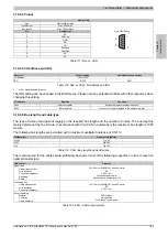
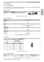
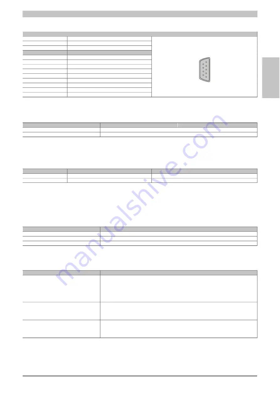
3.10.2.4 Pinout
Add-on CAN
Type
Electrically isolated
Transfer rate
Max. 500 kbit/s
Bus length
Max. 1000 meters
Pin
Assignment
1
NC
2
CAN low
3
GND
4
NC
5
NC
6
Reserved
7
CAN high
8
NC
9
NC
9-pin DSUB plug
5
1
9
6
Table 117: Pinout - CAN
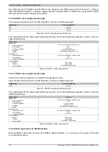
3.10.2.5 I/O address and IRQ
Resource
Default setting
Additional setting options
I/O address
384h / 385h
-
IRQ
IRQ10
NMI
1
Table 118: Add-on CAN - I/O address and IRQ
1
NMI = Non Maskable Interrupt.
The IRQ setting can be changed in the BIOS setup. Please note any potential conflicts with other resources when
changing this setting.
I/O address
Register
Function
384h
Address register
Defines the register number to access.
385h
Data registers
Access to the register defined in the address register.
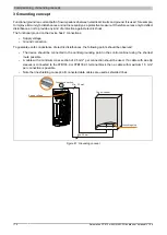
3.10.2.6 Bus length and cable type
The type of cable used depends largely on the required bus length and the number of nodes. The bus length is
mainly determined by the bit rate. In accordance with CiA (CAN in Automation) the maximum bus length is 1000
meters.
The following bus lengths are permitted with a maximum oscillator tolerance of 0.121%:
Distance [m]
Transfer rate [kbit/s]
≤ 1000
Typ. 50
≤ 200
Typ. 250
≤ 60
Typ. 500
Table 119: CAN - Bus length and transfer rate
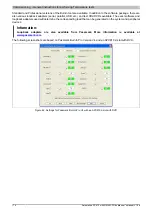
The material used for the cable should preferably have all or most of the following properties in order to reach an
optimal transfer rate.
CAN cables
Property
Signal lines
Cable cross section
Wire insulation
Conductor resistance
Stranding
Shield
2x 0.25 mm² (24AWG/19), tinned Cu wire
PE
≤ 82 Ω / km
Wires stranded in pairs
Paired shield with aluminum foil
Grounding line
Cable cross section
Wire insulation
Conductor resistance
1x 0,34 mm² (22AWG/19), tinned Cu wire
PE
≤ 59 Ω / km
Outer sheathing
Material
Features
Cable shielding
PUR mixture
Halogen-free
From tinned copper wires
Table 120: CAN - Cable requirements


