background image

 8BVI0014HWD0.000-1

Data sheet V 1.4

7

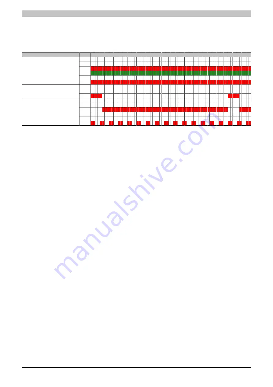
4.4 Status changes when booting the operating system loader

The following timing is used for the LED status indicators:
Block size: 50 ms

Repeats after: 3,000 ms

Status

LED

Indicator

RDY
RUN

1. Boot procedure for base hardware

active

ERR
RDY
RUN

2. Network configuration active

ERR
RDY
RUN

3. Waiting for network telegram

ERR
RDY
RUN

4. Network communication active

ERR
RDY
RUN

5. ACOPOS operating system being

transferred/burned 

1)

ERR

Table 7: Status changes when booting the operating system loader

1)

Firmware V2.140 and higher.

Summary of Contents for 8BVI0014HWD0.000-1

Page 1: ...at 2 2 interface 8BAC0121 000 1 ACOPOSmulti plug in module HIPERFACE interface 8BAC0122 000 1 ACOPOSmulti plug in module resolver interface 10 kHz 8BAC0123 000 1 ACOPOSmulti plug in module incremental...

Page 2: ...0014HWD0 000 1 General information B R ID code 0x26DF Cooling and mounting method Wall mounting Slots for plug in modules 2 Certification CE Yes KC Yes UL cULus E225616 Power Conversion Equipment Func...

Page 3: ...Max extinction energy per switching operation 1 5 Ws Max switching frequency 0 5 Hz Protective measures Overload and short circuit protection Yes Open circuit monitoring Yes Undervoltage monitoring Y...

Page 4: ...reases the CPU load When using 2 axis modules the increased CPU load reduces the functionality of the drive if this is not taken into consideration the computing time can be exceeded in extreme cases...

Page 5: ...Green Ready RUN Orange Run Inverter axis 2 ERR Red Error See inverter axis 1 Status of backup battery BAT Green Red Ready Error see Backup battery LED status indicators on page 6 Power supply 24 V Gr...

Page 6: ...ing green 2x Cyclic operation on the network is taking place but the client itself is not yet a participant Blinking green 3x Cyclic operation of the client is in preparation Solid green The client is...

Page 7: ...ts after 3 000 ms Status LED Indicator RDY RUN 1 Boot procedure for base hardware active ERR RDY RUN 2 Network configuration active ERR RDY RUN 3 Waiting for network telegram ERR RDY RUN 4 Network com...

Page 8: ...ientations Figure 2 Dimension diagram and installation dimensions 1 n Number of slots on the mounting plate 2 For proper air circulation at least 60 mm clearance must be available above the mounting p...

Page 9: ...B S2 B S2 T T T T X5B X5A U U V V W W PE PE X1 X2 S2 B S1 B Enable 1 COM 8 S2 B COM 5 S1 B Trigger2 Enable 2 COM 4 COM 1 COM 1 Enable 1 Trigger1 COM 7 24V Out 2 COM 3 24V Out 1 COM 9 Enable 2 ACOPOSmu...

Page 10: ...e g via the S1 S2 connections instead of via the internal transistor then the internal quenching circuit has no effect In this case the customer must make sure that neither the relay contact nor the b...

Page 11: ...that neither the relay contact nor the braking coil are damaged when switching off the brake This can be done by interconnecting the coil or better still interconnecting the contact with a quenching...

Page 12: ...e safely isolated circuits These connections are therefore only permitted to be connected to devices or components that have sufficient isolation in accordance with IEC 60364 4 41 or EN 61800 5 1 Caut...

Page 13: ...X5B connector Pinout X5B Name Function Axis 2 Protective ground conductor W Axis 2 Motor connection W V Axis 2 Motor connection V U Axis 2 Motor connection U W V U Table 14 X5B connector Pinout 6 1 8...

Page 14: ...lding brake Plug in module 8BAC0120 000 1 8BAC0121 000 1 8BAC0122 000 1 8BAC0123 00x 1 8BAC0124 000 1 Plug in module 8BAC0120 000 1 8BAC0121 000 1 8BAC0122 000 1 8BAC0123 00x 1 8BAC0124 000 1 8BAC0125...

Page 15: ...8BVI0014HWD0 000 1 Data sheet V 1 4 15 Figure 7 Motor...

Reviews: