X20 system modules • Counter modules • X20DC11A6
X20 system User's Manual 3.10
711
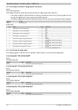
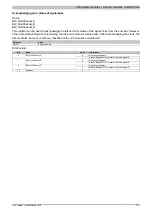
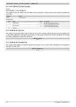
4.11.7.8.4.5 Counter value at the time of the last latch
Name:
Encoder01Latch
The counter value at the time of the last latch is displayed as a 16 or 32-bit value. Only the 16-bit value is available
in the bus controller function model.
Data type
Value
INT
-32768 to 32767
DINT
1)
-2.147.483.648 bis 2.147.483.647
1)
Can only be configured in the standard function model
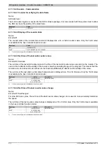
4.11.7.8.4.6 Counter value of latch event
Name:
Encoder01LatchCount
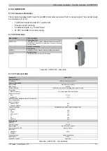
The latch events are counted and stored in a cyclic 8-bit counter. This counter is incremented with each latch event,
thereby indicating a new occurrence. The new latched counter value is stored in the respective latch register.
Data type
Value
SINT
-128 to 127
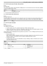
4.11.7.8.4.7 Encoder commands
Name:
Encoder01Command
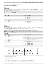
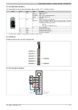
This register can be used to
1 reset the counter value. The counter is kept at zero until this command is reset.
2 enable the latch procedure. If the latch configuration is valid and matches the hardware signals, then this
activation causes the counter value to be saved in the latch register.
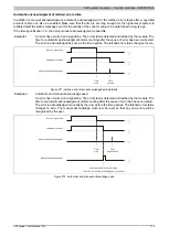
The two different latch configurations that are possible (see section 4.11.7.8.3.3 "Setting the latch mode") must
be handled as follows:
•
Single shot latch mode:
After successful latching, indicated by the latch event counter, activation must be reset before any more
latching is possible. The activation must be set again if additional latching is needed.
•
Continuous latch mode:
The latch function only has to be enabled/set as long as latching is desired. The latch event counter is
incremented with each event.
Data type
Value
USINT
See bit structure.
Bit structure:
Bit
Name
Value
Information
0
Do not reset
0
Encoder01Reset
1
Set encoder value to 0
0
Do not activate latch
1
Encoder01LatchEnable
1
Latching
2 - 7
Reserved
0
Summary of Contents for X20 System
Page 2: ......

