X20 system modules • Motor controllers • X20SM1436
2060
X20 system User's Manual 3.10
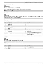
Motor ID
Name:
Motoridentification01
This register is used to identify the connected motor type for service purposes and to differentiate between motors
in the application. Following measurement, this register contains the time [µs] needed to apply a current increase
of ΔI = 1 A to a motor winding.
This depends on:
•
Operating voltage
•
Inductance and resistance of the motor winding
Notes
To achieve reproducible results, the measurement must be made under the following defined conditions:
a)
Motor is at standstill
1)
b)
The motor must be in a half-step position (phase A fully powered, phase B not powered). This means the internal position counter on the SM
module must have a value that fulfills the following conditions:
•
Full steps are divisible by 4
•
Microsteps = 0
2)
Condition 1b) is fulfilled after a the SM module is reset or powered on. Immediately afterwards, when the holding current is applied to the motor for the
first time (at standstill), the duration for applying the current is measured. This is therefore a suitable time to read the motor identification register in the
application.
3)
The current range from approximately 1/3 of the rated current up to the rated current is used as operating range for determining the motor identifier.
Data type
Motor ID values
Function
0
No motor identifier available (after turning on for as long as the measurement conditions are not
met)
1 to 32767
Valid range of values for the motor ID register (in µs)
65504 to 65519
Ground fault: Motor identification not possible
65528
Motor ID trigger not possible
•
Motor has no power applied
•
Motor in movement
•
Rated current is set to 0A
•
Ground fault present
65529
Invalid value: Underflow
65530
Overtemperature: Measurement not possible
65532
Open line: Measurement not possible
65533
Motor position incorrect: Measurement not possible
65534
Invalid value: Overrun
UINT
65535
Measurement in progress
Ground fault detection
When the motor is powered on, a ground fault check is performed before motor identification. Error numbers have
been added in the motor identification register for the event of a ground fault error (values 65504 to 65519 in the
table above).
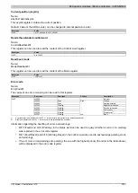
Homed zero position
Name:
RefPos01CyclicCounter
RefPos01AcyclicCounter
After a homing procedure, the homing position for the cyclic and non-cyclic position counter can be read using these
registers (either the internal position counter or ABR counter depending on bit 14 of the "Control word" register).
The following two registers are provided for the motor:
•
Homed zero position for cyclic counter
•
Homed zero position for non-cyclic counter
Data type
Value
DINT
-2,147,483,648 to 2,147,483,647
Summary of Contents for X20 System
Page 2: ......


