
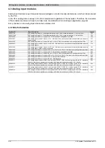


X20 system modules • Analog input modules • X20AI1744, X20AI1744-3
X20 system User's Manual 3.10
141
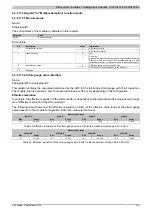
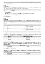
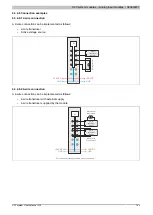
4.3.2.11.5 Register for "Multiple Sampling" function model
4.3.2.11.5.1 Module status
Name:
StatusInput01
The current state of the module is indicated in this register.
Data type
Value
USINT
See bit structure.
Bit structure:
Bit
Description
Value
Information
0
ADC value is valid
0
AD converter values
1
ADC value is invalid
0
OK
1
Line monitoring
1
Open line
An open line was found during at least one measurement in this
X2X cycle. This bit is reset if all measurements are OK after
correcting this error, i.e. it does not have to be acknowledged.
0
ADC runs synchronous to the X2X Link
2
Synchronous mode
1
ADC does not run synchronous to the X2X Link
3 - 7
Reserved
-
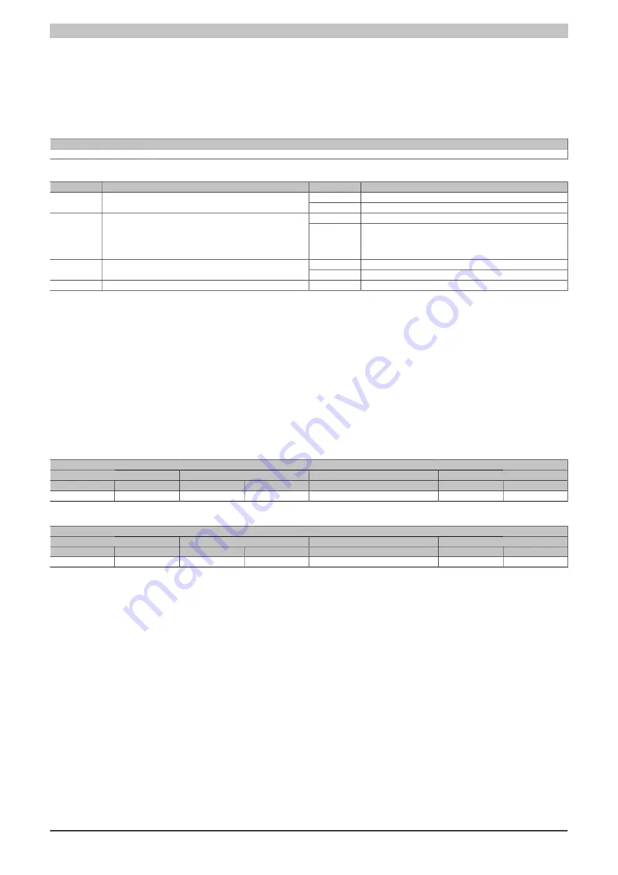
4.3.2.11.5.2 Strain gauge value - Multiple
Name:
AnalogInput01 to AnalogInput10
This register contains the raw value determined by the ADC for the full-bridge strain gauge with 16-bit resolution.
The module returns between 3 and 10 measured values per X2X cycle depending on the configuration.
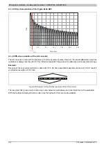
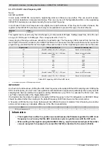
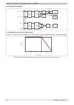
Effective resolution
In principle, the effective resolution of the AD converter is dependent on the data rate and the measurement range
(see "Effective resolution of the AD converter").
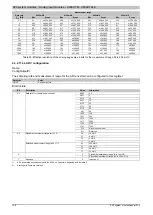
The following table shows how the effective resolution (in bits), or the effective value range of the strain gauge
value depend on the module configuration (data rate, measurement area).
Measurement range
±16mV/V
±8mV/V
±4mV/V
±2mV/V
Bits
Scope
Bits
Scope
Bits
Scope
Bits
Scope
15.4
22,000
14.6
12,000
13.8
7,000
12.8
4,000
Table 26: Effective resolution of the strain gauge value in bits for the measurement range 2 to 16 mV/V
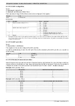
Measurement range
±256mV/V
±128mV/V
±64mV/V
±32mV/V
Bits
Scope
Bits
Scope
Bits
Scope
Bits
Scope
17.1
70,000
16.7
53,000
16.4
43,000
15.9
31,000
Table 27: Effective resolution of the strain gauge value in bits for the measurement range 32 to 256 mV/V
Summary of Contents for X20 System
Page 2: ......


