X20 system modules • Digital output modules • X20DO4613
1164
X20 system User's Manual 3.10
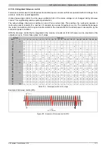
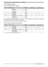
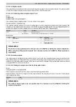
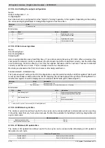
4.15.13.10.7.4 Switching behavior for zero-crossing errors
Name:
CfO_OutputTolerance
This register can be used to set the switching behavior of the trigger. After the number of zero-crossing errors
configured in Bit 0 to 4, the output is switched off for at least 3 periods. This is followed by synchronization with
the zero signal according to Bit 7.
Data type
Value
USINT
See bit structure.
Bit structure:
Bit
Description
Value
Information
0 - 4
Trigger for Resync
0 to 30
Number of zero-crossover errors
5 - 6
Reserved
-
0
Fast synchronization
7
Fast settling
1
PLL synchronization
Fast synchronization
With this option, the trigger point is closed-loop controlled after each individual zero-crossover and input jitter.
•
Advantage:
Increased tolerance and faster response to deviations in mains frequency
•
Disadvantage:
Increased switch-on jitter for firing signal by zero cross signal ±100 µSec
PLL synchronization
With this option the intervals between zero cross-overs are measured and the PLL frequency is updated accord-
ingly.
•
Advantage:
Jitter-free firing signal
•
Disadvantage:
When the output is switched off, additional measurement phases are required before it can
be switched back on.
Information:
This function is available starting with Firmware version 928. This can be installed with hardware ver-
sion 7 and hardware revision B4 or higher.
4.15.13.10.8 Status of the outputs
Name:
ZeroCrossingInput
ZeroCrossingStatus
StatusInput01
The operating status of the outputs is mapped in this register.
Function model 0 - Standard only:
The "packed outputs" setting in the AS I/O configuration is used to determine whether all of this registers' bits should
be set up individually as data points in the AS I/O mapping ("ZeroCrossingInput" through "ZeroCrossingStatus") or
whether this register should be displayed as an individual USINT data point ("StatusInput01").
Data type
Value
Information
0 to 255
Packed outputs = on
USINT
See bit structure
Packed outputs = off or function model <> 0 - Standard
Bit structure:
Bit
Name
Value
Information
0 - 3
Reserved
-
0
Zero cross signal during the negative half-wave
4
ZeroCrossingInput
1
Zero cross signal during the positive half-wave
5 - 6
Reserved
-
0
Zero cross signal OK
7
ZeroCrossingStatus
1
Zero cross signal has dropped out
Summary of Contents for X20 System
Page 2: ......


