background image

Recalling a Preset

To recall a preset from the SR10.1 remote control, press the preset number, then the ENTER button. For
example, to recall preset number 2, press 2 - ENTER.  Three steps are necessary in the case of a preset
above the number 10, (preset 12 = +10 - 2 - ENTER).  

To recall a preset from the front panel, press the PRESET button to scroll through the saved favorite presets.
Once the desired preset is found, press the ENTER button to recall the preset. 

If a preset is recalled in zone two, then the zone code for Zone B (002 default) must used to recall the preset.

Favorite Presets

The preamplifier saves a list of favorite presets which can be quickly accessed using the channel up/down
button on the remote, or the PRESET button on the front panel. The preamplifier can be setup to recall the
chosen favorites instantly or only after an ENTER command. When a preset is saved it is automatically
added to the favorites list. The list can be edited in the favorites menu (

page 30

). If there are no favorites in

the list, then CHANNEL or PRESET will step through all 40 presets.  

SR10.1 REMOTE EDITOR SOFTWARE

The SR10.1 is supplied with a CD-ROM containing the setup program.  This software can also be obtained
from the B & K website.  

After SR10.1 editor program has been installed, be sure to do a LIVE UPDATE.

The live update is found under Help ->Live Update.  A live update ensures that you have the latest version of
setup software.  Your PC will need to be connected to the internet to execute the update. The editor software
can be used to program your SR10.1 to control other source devices your system may contain.  The SR10.1
can be programmed to control devices such as DVD players, CD players, music servers, satellite set top
boxes, TVs, and more.  You can customize particular devices so frequently used commands are readily
accessible. 

The following pages summarize some key points of
the programming software.  The full version of the
programming manual is found under Help -> User
Guide or go to 

www.bkcomp.com. 

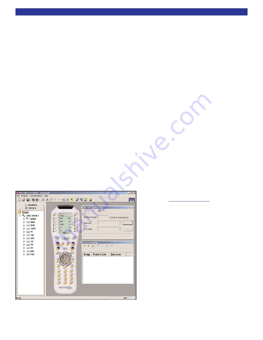
The SR10.1 comes pre-programmed with 10
devices.  Each device is pre-programmed on the
Main Page 1 of the SR10.1.  Each device button is
labeled to match the inputs on the back panel of the
preamplifier. Pressing a device button will change
the input on the preamplifier.  Once a device button
is pressed, the remote will automatically flip to page
one to display device functions. Page one of the
device can contain specific commands to control the
source component.  For example, pressing DVD will
change the preamplifier to the DVD input and then
show the controls for the DVD player.

The editor software can also be used to program
macros to further simplify the operation of your
system. A macro is a series of recorded IR steps
that can be executed with one button press.  A
simple macro might execute a preset recall, a more
complex macro can be setup to turn ON all source
devices or turn OFF all source devices. 

51

SR10.1 Editor

Summary of Contents for Series 2

Page 1: ...B K Components Ltd REFERENCE 51 SERIES 2 User Manual Seven Channel Surround A V Preamplifier Processor 13926 1105...

Page 2: ...ls its products through authorized dealers in order to ensure that consumers obtain proper dealer service and support Buying from an authorized B K Components Ltd dealer insures that you have a FACTOR...

Page 3: ...RD LOOP CONNECTIONS 18 CONTROL OUTPUT CONNECTION 18 IR Emitter Connection 18 12VDC Control Connection 19 ZONE B CONNECTIONS 19 Zone B Audio Amplification 19 Zone B Video Connection 19 REFERENCE 51 Ser...

Page 4: ...eadphone Operation 42 FRONT PANEL DISPLAY OPERATION 43 Processor Status 43 AUDIO MODES SPEAKER SELECTIONS 45 Audio Mode Usages 45 Speaker Selections 47 EQUALIZATION SETTINGS AND ADJUSTMENTS 48 PRESETS...

Page 5: ...g loss Do not operate for extended periods of time at high volume levels Protect the preamplifier from impact and place the preamplifier on a level surface The preamplifier is equipped with raised fee...

Page 6: ...ts are provided for superior transmission of audio material for up to two source components Two zone operation One main digital analog A V zone Theater Zone plus a separate independent analog A V zone...

Page 7: ...nd video to a video monitor An A V preamplifier requires the use of an external power amplifier Surround Processor A processor typically includes the capability to decode one or more surround formats...

Page 8: ...lt is increased background noise and decreased dynamic range and fidelity Digital signals are virtu ally immune to noise and distortion The preamplifier can therefore reproduce the signal with the gre...

Page 9: ...recordings Dolby Pro Logic IIx Dolby Pro Logic IIx is a new extension of Dolby Pro Logic II technology This highly sophisticated algorithm processes native stereo audio signals and 5 1 channel multi...

Page 10: ...c steers the effects into the soundfield by utilizing the surround channels for a more spacious 3 dimensional feeling When listening to music using the DTS Neo 6 music decoder stereo music recordings...

Page 11: ...also contain a 5 1 surround sound mix DSD s simplified mechanism for recording and playback results in a frequency response over 100kHz and a dynamic range over 120dB across the audible frequency ran...

Page 12: ...ifier ON STANDBY places the unit in standby mode that allows turning back on with the remote control Only turn the preamplifier off with the main power switch when not using the preamplifier for an ex...

Page 13: ...ing the second zone Configurable fixed or variable Page 19 9 Balanced Surround XLR outputs Connections for 7 1 speakers in the main theater zone Page 15 10 Balanced Source XLR Inputs The CD and or DVD...

Page 14: ...est from B K s customer service The setup software is easy to use and is intended to simplify the setup process of your new B K products Configure a system diagram of all components that are to be con...

Page 15: ...See Video Monitor Connection page 14 for details on connecting a video monitor If the second zone of the surround preamplifier or the record loop outputs are going to be used the analog audio and com...

Page 16: ...site or S If no component assignment is made to a particular input the component output will be transcoded from the appropriate composite or S video input The preamplifier automatically detects the pr...

Page 17: ...ut section on the back panel is labeled Surround Outputs See page 17 for a connection diagram using the coaxial connections For best acoustic results be sure to set up the speakers using the speaker s...

Page 18: ...ION RISK OF ELECTRIC SHOCK DO NOT OPEN RISK OF ELECTRIC SHOCK DO NOT OPEN B K S B IMPLY ETTER IR INPUT ZONE B EXPANSION OUTPUT BALANCED SURROUND OUTPUTS SUBWOOFER BALANCED LINE INPUTS RIGHT LEFT RIGHT...

Page 19: ...ct the center channel output to the center speaker amplifier channel If a 5 channel audio system is desired do not connect the surround back audio channels If a 6 channel audio system is desired conne...

Page 20: ...the analog audio and video from whatever input is selected in Zone A LtRt mode will downmix a digital bitstream to left and right Record Line settings also apply to the Zone A optical and coaxial dig...

Page 21: ...video output signals are connected from the Zone B outputs on the back panel of the pream plifier to a Zone B video monitor and a Zone B amplifier Zone B Audio Amplification To connect an amplifier f...

Page 22: ...REFERENCE 51 Series2 ZONE B CONNECTION DIAGRAM 20...

Page 23: ...pressing the backlight button ZONE A ZONE B IR INPUTS Two IR inputs are located on the back panel of the preamplifier They are labeled IR IN Zone A Zone B The IR inputs use a 3 5mm mono mini jack Inte...

Page 24: ...repeatedly until you leave the menu system UP DOWN ARROWS Once you are in the menu system use the UP DOWN ARROWS to move to the desired menu selection With the supplied SR10 1 remote rocking the thum...

Page 25: ...e adjusted Page 24 2 Unit Information Contains information about the unit make model serial number software version BKC DIP version phase locked loop chip version This information may be needed when c...

Page 26: ...to be saved The presets can then be recalled at a later time See page 30 4 Setup Displays This configures the preamplifier for preferences relating to the front panel and on screen displays To setup t...

Page 27: ...t Surround Speakers It is not necessary to have surround speakers Set them to small or large based on the guidelines above Or if there are no surround speakers set them to none The surround infor mati...

Page 28: ...nt to them Gradual transitions with higher crossover settings can also cause the perceived location of a sound to move from the correct main speaker location Normally you will want to use identical sl...

Page 29: ...s the frequency response At higher frequencies hundreds of small peaks and dips can be measured in the frequency response Attempts to remove all these small deviations would result in colorations to t...

Page 30: ...ator at 30dB Sweep the frequency range to locate the 3 highest peaks Using an SPL meter note the frequency and the level of these peaks Also note the frequencies above and below the peak where the lev...

Page 31: ...matically correct for this with no loss of audio information NOTE If it is preferred that the default speakers and default audio mode to apply to multi channel audio Manual Surround mode must be selec...

Page 32: ...ic name consists of the source input and volume level The name can be changed before saving the preset The automatic naming can be defeated so that a custom title that was previously entered will not...

Page 33: ...settings can be adjusted on the fly using the remote The settings will always return to the settings in this menu when you first select the music mode See page 7 for a description of what these settin...

Page 34: ...If the IR or front panel has been locked this button press sequence will unlock them After enabling advanced menu the system setup menu will change Advanced Locked Advanced Unlocked U UN NI IT T I IN...

Page 35: ...ing device in Zone A TAPE The V1 output can also be configured as a Zone A line output to connect a second video monitor and or audio amplifier LINE As a record output V1 will output the analog audio...

Page 36: ...to the control output An IR emitter can be connected for control of an IR device IR will only pass through when the source is selected and the control is set for remote RS 232 The control output can b...

Page 37: ...lifier with a B K remote or RS 232 computer Interface Note if you inadvertently lock the front panel simultaneously pressing STANDBY UP and DOWN on the front panel will always enter the advanced secur...

Page 38: ...Reply message the Reference 51 Series2 will automatically generate when a master volume change is executed in Logical Zone 1 is 0 R P1 FF 1 60 Reply message Logical Zone 1 current Preset parameter Vo...

Page 39: ...te when a digital signal first appears or changes modes Most notably some DVD recorders output about 1 5 seconds of invalid digital bitsreams after you close the drawer Digital Sticky 2 5 Only applies...

Page 40: ...output V2 will output the analog audio and video from whatever input is selected in Zone B Link input to Zone A YES or NO The second zone s source selection may be linked with the Zone A source select...

Page 41: ...he source associated with the input on the B K preamplifier The setup software contains a database of various manufacturers IR codes for devices such as DVD players CD players music servers TVs and mo...

Page 42: ...fier in STANDBY or by using the ON and OFF buttons of the remote control Standby mode keeps minimal functions running in order to allow the remote control or keypad to quickly power the unit up Note t...

Page 43: ...scroll down and select choice four Z2 Operation 2nd Zone The audio input and video input can be selected independently If the V2 input is selected the V2 output for recording can selected independent...

Page 44: ...front panel select a source press the MODE button Press the UP or DOWN arrows to step through until the preamplifier switches into headphone mode When in headphone mode CONTROL OUT 1 is set to off def...

Page 45: ...o mode speaker selections EQ setting and surround processing types The video source type is very important if you are mixing component composite and S video types It will describe the video type the p...

Page 46: ...L2X MU 5 NEO6 MU 5 NEO6 MV 5 PL2X MV 5 PL2X MU 5 NEO6 MU 5 NEO6 MV 5 5 Backs Mono 5B STEREO 5B PL2X MV 5B PL2X MU 5B NEO6 MU 5B NEO6 MV 5B PL2X MV 5B PL2X MU 5B NEO6 MU 5B NEO6 MV 5B 6 Mono 6 STEREO 6...

Page 47: ...udio Mode Usages MONO The audio signals are summed or downmixed to produce a single mono channel which can then be distributed evenly to the desired number of speakers It is also useful in the case of...

Page 48: ...reamplifier will automatically select SURROUND 6 for ES DSC material Cinema Mode CINEMA mode is identical to SURROUND mode except that it adds high frequency roll off to the front and center channels...

Page 49: ...rround or back speakers When the system setup is correctly performed the preamplifier will route audio to fewer small speakers with the needed corrections to volume and down mixing applied automatical...

Page 50: ...volume levels 3 Vocal Frequency gains have been cut on both the high and low end for vocals only listening This is useful for late night listening as it allows you to hear the dialogue but reduces th...

Page 51: ...dure that is used to setup and save a preset The procedure references the SR10 1 Remote Control that came with the Reference 51 Series 2 preamplifier Step 1 First setup the preamplifier for the desire...

Page 52: ...ht to move to a different character Press ENTER again to save the name From the front panel use UP or DOWN buttons to change the character and the volume knob to mode to a different character To save...

Page 53: ...ures that you have the latest version of setup software Your PC will need to be connected to the internet to execute the update The editor software can be used to program your SR10 1 to control other...

Page 54: ...n displays the list of commands within a device Once you select the command you want to shortcut to click SAVE The diagram below illustrates putting the B K command for the NEO 6 decoder in the DVD de...

Page 55: ...IR code A learned code can be pressed or pressed and held for a sustained burst All buttons can be programmed with learned codes including all MAIN buttons hard and LCD except the buttons on FAV page...

Page 56: ...C setup should follow the described procedure 1 Open BKcSuite A V Setup from BKTask DO NOT CONNECT UNIT TO COMPUTER Without a connection to the preamplifier is considered virtual mode 2 When BKcSuite...

Page 57: ...Double click the COM port corresponding to the port the CT CK SR product is physically connected to and go to section 6 below 6 Set the proper communication properties The parameters for Port Settings...

Page 58: ...56 THIS PAGE INTENTIONALLY LEFT BLANK...

Page 59: ...57 THIS PAGE INTENTIONALLY LEFT BLANK...

Page 60: ...ituting cables Remote Keypad IR sensor s will not work 1 Batteries dead missing installed wrong 2 IR lock is enabled 3 IR inference 4 Using the wrong IR code set 5 Wires are crossed 1 Check and replac...

Page 61: ...ONENT VIDEO AM FM ANTENNA ZONE B OUTPUTS ZONE B FRONT SURRND S BACK CENTER SUB SURROUND OUTPUTS OPTICAL S PDIF DIGITAL COAX S PDIF DIGITAL OUT SAT CD DVD V2 V1 V1 V2 TV ZA OUT ZB OUT SAT CD DVD CONTRO...

Page 62: ...60 Reference 51 Series 2 Menu System ON SCREEN MENU FLOW CHART...

Page 63: ...ROL OUT SETUP 1 Control Out 1 2 Control Out 2 3 Control Out 3 4 Control Out 4 SECURITY OPTIONS 1 Advanced Men Visible 2 Memory Locked No 3 Front Locked No 4 IR Locked No RS 232 PORT SETUP 1 Port Enabl...

Page 64: ...rol Outputs Four 10 12VDC triggers 50mA Dimensions in Inches Width Cutout Dimensions Height Depth 17 00 17 12 5 75 7 87 13 5 14 62 Shipping Weight 20 lbs Power Consumption 30 watts max Replacement Fus...

Reviews: