B&K Reference 125.2 S2 User Manual Download Page 10

CONTROL TRIGGERS

A control (trigger) system is provided on the Reference 125.2 S2 amplifiers to allow remote switching of the
amplifier's standby on/off feature. The control input is designed to operate with a source (trigger) of 5-24 volts
DC.  All B&K A/V processors and preamplifiers utilize control output triggers to easily integrate an amplifier
into an audio system. 

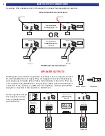
In addition, your amplifier has a control output circuit to allow control of an external device such as another
power amplifier, projection screen, power strip, etc. The control output has the capability to source 10-12VDC
@ 200 mA (on) or 0 VDC (off).

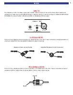
If more than one amplifier is being controlled, the control output may be extended to include each successive
unit by simply connecting a 3.5mm (1/8”) mini-jack cable from the CTRL OUT connector of the first amplifier
to the CTRL IN connector of next amp (commonly referred to as 'daisy chaining'). An example of how to con-
nect two amplifiers is illustrated in the diagram below.

Daisy Chained Control I/O

DO NOT POWER MOTORS WITH THE CONTROL OUT CIRCUIT!!!

If the control function is desired, each unit in the system must remain connected. The control is enabled when
the 3.5mm jack is inserted into the CTRL IN. For more information on the amplifier's output status under vari-
ous control conditions, refer to the table below.

*Note: The control input voltage is intended for standby on/off control only. For best amplifier operation, each
amplifier should have its own source of AC power.

Operational Outline

Hardware (3.5mm)

@ CTRL IN

Output Status

@ CTRL OUT

Not Connected

No Voltage

Sound

+12V

Connected

No Voltage

No Sound

0V

Connected

Voltage

Sound

+12V

Rear view of second

amplifier with control I/O

Rear view of first amplifier

with control I/O

Daisy chain to

other amplifiers

Connects to

preamp control output

C O N T R O L I / O

C O N T R O L I / O

CONTROL IN ALLOWS AMPLIFIER

OPERATION WHEN A 5-24V SIGNAL

IS APPLIED WITH A 3.5mm MINI JACK

CONTROL IN ALLOWS AMPLIFIER

OPERATION WHEN A 5-24V SIGNAL

IS APPLIED WITH A 3.5mm MINI JACK

C T R L

O U T

1 2 V D C
2 0 0 m A

C T R L

O U T

1 2 V D C
2 0 0 m A

C T R L

I N

C T R L

I N

+12V

L

O

W

P

OWER

+12V

L

O

W

P

OWER

RING

RING

TIP

TIP

GROUND

GROUND

SLEEVE

SLEEVE

+12V

CTRL

ENABLE

+12V

CTRL

ENABLE

8

Summary of Contents for Reference 125.2 S2

Page 1: ...B K Components Ltd User Manual REFERENCE 125 2 S2 Two Channel Amplifier 13746 0604...

Page 2: ...insures that you have a FACTORY WARRANTY on your B K Components Ltd product If you have any questions concerning your Factory Warranty call B K Components Ltd at 716 656 0026 Upgradability B K is one...

Page 3: ...S 1 SAFETY PRECAUTIONS 2 PURPOSE AND FUNCTION 3 BACK PANEL 4 INPUTS 5 INPUT OUTPUT CONNECTIONS 6 SYSTEM INSTALLATION 7 CONTROL TRIGGERS 8 TROUBLESHOOTING 9 SPECIFICATIONS Back Cover 1 Date of Purchase...

Page 4: ...gainst removing or altering feet Do not stack anything on top of the amplifier processor source etc Leave a minimum of 3 clearance from the top of the amplifier to the next shelf or component to insur...

Page 5: ...with minimum signal loss and degradation Five Way Binding Posts High quality binding posts accommodate up to 4 gauge wire Control Output One 3 5mm 1 8 10 12 VDC 200 mA output for controlling other am...

Page 6: ...place only with the same type and value fuse 2 AC Input Receptacle For attaching the supplied AC power cord to the amplifier 3 Speaker Outputs For connecting the speakers to the amplifier Explained fu...

Page 7: ...125 2 S2 These connectors accept balanced vol ume level output from the preamplifier s balanced output connectors RCA UNBALANCED There are two unbalanced RCA input connectors on the Reference 125 2 S...

Page 8: ...They are color coded for easy identification The positive RED post should always be connected to the speakers RED jack The negative BLACK post should always be connected to the speakers BLACK jack Sho...

Page 9: ...anel is in the off position and AC power is disconnected before making any connections Connect the wires from your speakers to the appropriate output channels on the amplifier It is essential that cor...

Page 10: ...OTORS WITH THE CONTROL OUT CIRCUIT If the control function is desired each unit in the system must remain connected The control is enabled when the 3 5mm jack is inserted into the CTRL IN For more inf...

Page 11: ...orts or overloading 4 Supply Control IN with a 5 24 Volt DC supply Page 8 5 Push in power switch No sound on some or all selected channels power on LED illuminat ed 1 Speaker leads loose or faulty 2 P...

Page 12: ...vity XLR Balanced 2 8 Volts Pin 1 Gnd Pin 2 In Pin 3 In Gain 28 3AV or 28dB AC Line Voltage 120 220 240 VAC optional switchable Level Controls No Binding Post Maximum Wire Gauge 4 AWG Balanced Inputs...

Reviews: