B&K Phono10 Owner'S Manual Download Page 8

PHONO STAGE 

The phono stage of the Phono 10 may be configured for either Moving Magnet (MM) or Moving Coil (MC) 
applications with the additional capability to set the resistive and capacitive loading of the phono cartridge. 

Note: 

Your Phono 10 has already been configured for a MM stage with a resistive load of 50 Kohms. You do not have to 
perform any modifications unless you so desire. To reconfigure your Phono 10, follow the appropriate procedure 
listed below. 
 

IMPORTANT - ENSURE THAT THE POWER CORD IS DISCONNECTED FROM THE AC 
OUTLET PRIOR TO PERFORMING ANY OF THE FOLLOWING PROCEDURES! 


SELECTING MOVING MAGNET / MOVING COIL 

1. 

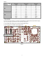
Locate the 2-position slide switch on the inside of the unit (see Figure 2). It is located near the back left side 

with the front of the unit facing you. The switch can be identified by its blue color and white tab in the center. MC 
and MM are labeled on the board on either side of the switch. 

 
2. 

Slide the center white tab left or right to select the type of phono stage that is desired.  

Left = Moving Coil (MC), Right = Moving Magnet (MM). 

 
NOTE: 

The Phono 10 is shipped from the factory with the phono stage set to the MM configuration and a resistive 

load of 50 Kohms. Selecting the MC stage without changing the resistive loading (see “Resistive Loading”) will 
result in an effective load of 133 ohms. 


Figure 2 


Summary of Contents for Phono10

Page 1: ...P N12839 0902 B K S B IMPLY ETTER B K Components Ltd Phono 10 Owner s Manual...

Page 2: ...ii B K Components Ltd 2100 Old Union Road Buffalo New York 14227 2725 Phone 1 800 543 5252 or 716 656 0026 Fax 716 656 1291 E mail info bkcomp com Web www bkcomp com...

Page 3: ...gn and Construction 4 Phono 10 Connections 4 Phono Stage 5 Selecting Moving Magnet Moving Coil 5 Capacitive Loading 6 Resistive Loading 6 Control I O Connections 8 Gain Switch 9 Digital Output 9 Troub...

Page 4: ...ance servicing instructions in the literature accompanying the unit Observance of polarity is essential Double check connections before turning the receiver or preamplifier on The Phono 10 can be dama...

Page 5: ...d better sound Control I O Circuit allows for power on and off muting and external control for other components Direct coupled output Provides a full and accurate three dimensional reproduction of sou...

Page 6: ...NTROL I O CONTROL I O DEFEAT ENABLE OUT IN 12V 35mA 1 Control I O 5 Ground Binding Post 2 Gain Switch 6 Digital Output 3 Analog Outputs 7 AC Receptacle 4 Analog Inputs 1 Control I O For remote turn on...

Page 7: ...ONO 10 CONNECTIONS All leads should be connected securely to the input and output terminals Loose connections can lead to impaired performance noise interference and possible damage to your equipment...

Page 8: ...F THE FOLLOWING PROCEDURES SELECTING MOVING MAGNET MOVING COIL 1 Locate the 2 position slide switch on the inside of the unit see Figure 2 It is located near the back left side with the front of the u...

Page 9: ...oil This resistor should not be removed unless the resistive loading is being changed in accordance with the following guidelines 1 Determine the resistor value for proper loading of the cartridge in...

Page 10: ...8 k 53 6 k 50 0 k 100 0 k 100 k MM 75 0 k 300 0 k 301 k Factory Installed 2 With the front of the unit facing you locate the two gold plated pin receptacles with the label RLOAD between them They are...

Page 11: ...st be within the range as indicated on the rear panel 5 24V DC The Phono 10 s CONTROL OUT will provide each successive component with a control voltage of 12V DC for reliable operation The Phono 10 s...

Page 12: ...ut signal level is 0 dB When the switch is OUT the output level is decreased by 10 dB NOTE If the Phono 10 has Digital Output capability the digital output level is related to the setting of the gain...

Page 13: ...and Phono 10 1 Check all connectors and repair as necessary 2 Check ground of outlet Have it checked by qualified serviceman 3 Reposition cables 4 Connect phono ground Sound is lower in volume compar...

Page 14: ...ad Resistance Variable Moving Load Capacitance Variable Moving Magnet S N A Weighted 89 dB Input Impedance 50 k Ohms Output Impedance 221 Ohms Maximum Output Level 9 V RMS Frequency Response 5 Hz 20 k...

Page 15: ...des B K delivers exceptional value to its customers But what is Upgradability Upgradability is not a guarantee we define it as a philosophy of designing and manufacturing products so that as audio tec...

Page 16: ...13 WWW BKCOMP COM B K Components Ltd 2100 Old Union Road Buffalo New York 14227 Phone 716 656 0026...

Reviews: