background image

DownScan

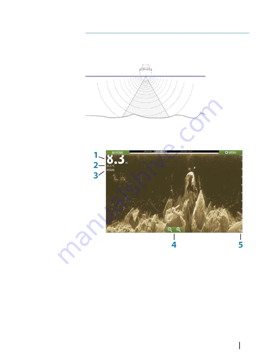
DownScan provides detailed images of structure directly below
your boat, down to 92 m (300 ft). The DownScan page is accessed
from the Home page when the DownScan transducer is connected.

The DownScan image

1

Depth

2

Temperature

3

Frequency

4

Zoom buttons

5

Range scale

11

DownScan

| Vulcan Operator Manual

87

Summary of Contents for Vulcan

Page 1: ...ENGLISH Vulcan Operator Manual bandg com...

Page 2: ......

Page 3: ...relating to the product Documentation may be translated to or has been translated from another language Translation In the event of any conflict between any Translation of the Documentation the Engli...

Page 4: ...under DownScan Imaging DownScan DownScan Overlay Overlay GoFree GoFree SonicHub SonicHub Copyright Copyright 2015 Navico Holding AS Warranty The warranty card is supplied as a separate document In cas...

Page 5: ...from the reader is emphasized as follows Note Used to draw the reader s attention to a comment or some important information Warning Used when it is necessary to warn personnel that they should proce...

Page 6: ...l memory Use the menu options and on screen buttons to maneuver in the pdf file as described below Search Goto page Page Up and Down Select the relevant panel button Scroll pages Drag finger on the sc...

Page 7: ...rsion currently on this unit can be found in the About dialog The About dialog is available in the System Settings For information regarding upgrading your software refer to Software upgrades on page...

Page 8: ...8 Preface Vulcan Operator Manual...

Page 9: ...Overboard waypoint 23 Screen capture 24 Customizing your system 24 Customizing the Home page wallpaper 24 Adjusting panel size 25 Adding new favorite pages 26 Edit favorite pages 26 Setting the appear...

Page 10: ...54 Navigating with the autopilot 55 Navigation settings 57 The Sail Steer panel 58 Selecting data fields for the Sail Steer panel 58 Sail Time calculations 59 Time and Wind plots 59 The Time plot pane...

Page 11: ...sounder image 83 Recording log data 85 Echosounder settings 87 DownScan 87 The DownScan image 88 Zooming the DownScan image 88 Using the cursor on the DownScan panel 88 Viewing DownScan history 89 Set...

Page 12: ...109 Waypoints routes tracks 109 Tides 109 Alarms 109 Settings 110 Vessels 110 Sun Moon 110 Trip calculator 110 Files 110 Find 111 Simulator 111 Demo mode 111 Simulator source files 112 Advanced simul...

Page 13: ...mation 2 Applications Select a button to display the application as a full page panel Press and hold a button to display pre configured split page options for the application 3 Close button Select to...

Page 14: ...tion pages are accessed from the Home page 1 Application panel 2 Instrument bar Navigation and sensor information The bar can be turned off and it can be configured by the user 3 System controls dialo...

Page 15: ...selected application combined with each of the other panels Note The number of pre configured split pages cannot be changed and the pages cannot be customized or deleted Access a pre configured split...

Page 16: ...ge 101 for more information BEP CZone integration The Vulcan integrates with BEP s CZone system used for controlling and monitoring a distributed power system on your vessel The CZone icon is availabl...

Page 17: ...nd setup are described in the Vulcan Installation manual Note For safety reasons Autopilot and CZone functions cannot be controlled from a wireless device Operating the system with a wireless device W...

Page 18: ...dialog Activating functions Select the icon of the function you want to set or toggle on or off For those functions that toggle on and off a highlighted icon indicates the function is activated as sh...

Page 19: ...set backlight levels by short presses on the Power key Night mode The night mode option optimizes the color palette and backlight for low light conditions Note Details on the chart may be less visible...

Page 20: ...tatus of the cursor active vs inactive changes the menu options Dialog boxes A dialog is closed by saving or cancelling the entry A dialog can also be closed by selecting the X in the dialog s upper r...

Page 21: ...on on the image by positioning the cursor on the panel then using the Goto Cursor option in the menu The Cursor assist function The cursor assist function allows for fine tuning and precision placemen...

Page 22: ...icon follows the vessel as the vessel moves while the blue icon remains at the position given when you activated the function You terminate the measuring function by selecting the Finish measuring men...

Page 23: ...ption in the dialog A MOB waypoint can also be deleted from the menu when it is activated Screen capture You need to turn on the Screen capture option in the System Settings dialog to be able to take...

Page 24: ...sen as the wallpaper it is automatically copied to the Wallpaper folder Adjusting panel size You can change the panel size for an active split page The panel size can be adjusted for both favorite pag...

Page 25: ...to open the page editor dialog 2 Drag and drop page icons to set up a new page 3 Change the panel arrangement only possible for 2 or 3 panels if required 4 Save the page layout The system displays th...

Page 26: ...Note This only turns the Instrument bar off for the current page Turning the Instrument bar on off 1 Activate the System controls dialog 2 Deactivate activate the instrument bar icon to toggle the bar...

Page 27: ...place waypoints and display AIS targets The Chart panel 1 MOB Man Over Board mark 2 Vessel with extension line extension line is optional 3 Waypoint with Laylines 4 North indicator 5 Route 6 Grid lin...

Page 28: ...le charts please visit insightstore navico com c map jeppesen com or navionics com Note The system does not automatically switch to embedded cartography if the chart card is removed A low resolution c...

Page 29: ...u have identical charts available built in or in the card slot the system automatically selects the chart with most chart details for your displayed region Vessel symbol When the Vulcan has a valid GP...

Page 30: ...in the direction of the next waypoint when navigating a route or navigating to a waypoint If not navigating the heading up orientation is used until navigation is started Look ahead Moves the vessel i...

Page 31: ...The Clear cursor and Restore cursor options are useful features for toggling between the vessel s current location and the cursor position Creating routes You can create routes as follows on the char...

Page 32: ...chart option is selected the Pan and the Rotate icons appear on the right side of the chart panel Panning the 3D chart You can move the chart in any direction by selecting the Pan icon and then panni...

Page 33: ...described in this section are common for all chart types Chart imagery style The charts can be displayed in three imagery styles 2Dmappingstyle Shadedrelief Nocontours Insight view options Chart detai...

Page 34: ...oughs in water to make them look taller or deeper Navionics specific chart options Orientation Look ahead 3D and change Chart source previously described in this section are common for all chart types...

Page 35: ...s of geographical layer information Safety depth The Navionics charts use different shades of blue to distinguish between shallow and deep water Safety depth based on a selected limit is drawn without...

Page 36: ...currents evolution over time Dynamictideinformation Dynamiccurrentinformation The following icons and symbology are used Current speed The arrow length depends on the rate and the symbol is rotated a...

Page 37: ...w satellite photo images of an area as an overlay on the chart The availability of such photos is limited to certain regions and cartography versions You can view photo overlays in either 2D or 3D mod...

Page 38: ...urposes The range is only as accurate as the underlying chart data meaning that if the chart only contains 5 meter intervals for contour lines the shading is rounded to the nearest available contour l...

Page 39: ...n for that location are displayed Dynamic current data can be viewed by zooming inside a 1 nautical mile zoom range At that range the Current icon changes to an animated dynamic icon that shows the sp...

Page 40: ...ngs The boat settings are used when calculating an automatic route The boat s draught width and height must be input to use the autorouting and easy routing features Range Rings The range rings can be...

Page 41: ...options are turned on for the vessel then no extension lines are shown for your vessel Your vessel heading is based on information from the active heading sensor and the COG is based on information fr...

Page 42: ...tersection Length Sets the length of the laylines Target wind angle Defines the target for the TWA True Wind Angle The target can be read from your polar table it can be read from the live measurement...

Page 43: ...titude grid lines on the chart Course highway Adds a graphic presentation of cross track error XTE limits to the route For setting the XTE limit see XTElimit on page 55 Waypoints Routes Tracks Turns o...

Page 44: ...You can save a waypoint at a selected location by positioning the cursor on the panel and then selecting the new waypoint option in the menu In the Chart and Nav panels you can save a waypoint at the...

Page 45: ...by selecting the Delete menu option when the waypoint is activated You can also delete waypoints from the Waypoints tool on the Home page You can delete MOB waypoints the same way Waypoint alarm sett...

Page 46: ...ion from the menu 3 Position the first waypoint on the chart panel 4 Continue positioning new routepoints on the chart panel until the route is completed 5 Save the route by selecting the save option...

Page 47: ...is located in an unsafe area A warning dialog is displayed and you have to move the relevant routepoint s to a safe area to proceed Note If no compatible cartography is available the Autorouting or Ea...

Page 48: ...the routepoints positions 6 Eventually repeat step 2 Selection and step 3 if you want the system to automatically position routepoints for other parts of the route 7 Select Save to complete the automa...

Page 49: ...tool on the Home page Converting Tracks to Routes You can convert a track to a route from the Edit Track dialog The dialog is activated by activating the track then selecting the track s pop up or by...

Page 50: ...ave travelled Tracks can be converted to routes from the Edit dialog From the factory the system is set to automatically track and draw the vessel s movement on the chart panel The system continues to...

Page 51: ...frequency of the recording You can select to position track points based on time settings distance or by letting the system position a waypoint automatically when a course change is registered Note T...

Page 52: ...Tracks dialogs The Waypoints Routes and Tracks dialogs give access to advanced edit functions and settings for these items The dialogs are accessed from the Tools panel on the Home page 52 Waypoints V...

Page 53: ...cursor at the selected destination on the panel and then select the Goto Cursor option in the menu Note The Goto Cursor menu option is not available if you are already navigating Navigate a route You...

Page 54: ...ncludes an option for cancelling the navigation Navigating with the autopilot When you start navigation on a system with autopilot functionality you are prompted to set the autopilot to navigation mod...

Page 55: ...due north south or along the equator Rhumb lines are tracks of constant bearing It is possible to travel between two locations using Rhumb line computation but the distance would usually be greater t...

Page 56: ...own local magnetic variation Datum Most paper charts are made in the WGS84 format which also is used by the Vulcan If your paper charts are in a different format you can change the datum settings acco...

Page 57: ...page The number of data fields included in the panel is dependent on available panel size 1 User configurable data fields 2 Vessel heading 3 COG Course Over Ground 4 Apparent wind 5 Port and starboard...

Page 58: ...op of the panel 3 Select the instrument field you want to change The selected field has a highlighted frame 4 Select the MENU button again to select info 5 Repeat the steps to change other instrument...

Page 59: ...flattens out at the point the data was lost When the data becomes available again a dashed line joins up the two points showing an average trend line bridging the missing data Selecting data Each dat...

Page 60: ...gned to help you understand recent changes in wind speed and direction The Wind Plot panel includes wind direction and wind speed The graphics are configured vertically with the newest data being disp...

Page 61: ...he autopilot Warning An autopilot is a useful navigational aid but DOES NOT replace a human navigator Activating the autopilot You activate the autopilot from any panel by selecting the autopilot tile...

Page 62: ...e or locked by another autopilot control unit Autopilot pop up You control the autopilot from the autopilot pop up The pop up has a fixed position on the page and it is available for all pages except...

Page 63: ...Turn pattern selection Autopilotcontroller Modeselection Turnpatternselection Autopilot tile in Instrument bar You can select to show the autopilot tile in the Instrument bar If the autopilot pop up...

Page 64: ...e helm Compass and rudder angle is shown on the display NFU Non Follow Up steering where the rudder movement is controlled by using the Port and Starboard keys in the Pilot pop up or by another NFU un...

Page 65: ...oute Standby mode Standby STBY mode is used when you steer the boat at the helm Non Follow Up NFU Power steering In NFU mode you use the port and starboard arrow buttons in the autopilot pop up to con...

Page 66: ...autopilot pop up and then entering the desired heading value An immediate heading change takes place The new heading is maintained until a new heading is set Heading capture When the vessel is turning...

Page 67: ...the original heading due to current and or wind the vessel follows the line with a crab angle 1 Turn the vessel to the desired heading 2 Activate the NoDrift mode The autopilot draws an invisible bear...

Page 68: ...you reject this request you can start NAV mode from the autopilot mode menu When NAV mode is initiated the autopilot automatically keeps the vessel on the leg When the vessel reaches the arrival circl...

Page 69: ...waypoint circle when creating the route X axis Boat speed in knots Y axis Arrival circle radius in 1 100 Nm Example With the speed of 20 knots you should use a waypoint circle with radius 0 09 Nm Note...

Page 70: ...d out in calm sea conditions with light wind to find out how it works on your boat Due to a wide range of boat characteristics from cruising to racing boats the performance of the tack function may va...

Page 71: ...ng it is difficult to steer the boat with waves coming sideways or from behind The waves can yaw the boat into an unwanted gybe this can be hazardous for both the crew and the mast The gybe prevent fu...

Page 72: ...a turn you can select STBY in the autopilot pop up to return to STBY mode and manual steering Turn variables The turn steering options except the C turn have settings that you can adjust before you s...

Page 73: ...leg distance Square turn Makes the vessel automatically turn 90 after having travelled a defined leg distance At any time during the turn you can change the main heading and the distance of the leg u...

Page 74: ...parameter determines the ratio between commanded rudder and the deviation from the selected depth contour The higher depth gain value the more rudder is applied If the value is too small it takes a lo...

Page 75: ...en the remote lock function is enabled on an AP24 AP28 control unit only the active control unit stays in command No transfer of command to Vulcan or other autopilot control units on the system can ta...

Page 76: ...this is indicated with a lock symbol and with text in the pop up No automatic modes can be selected from a locked unit Note The lock function is not available on a unit which has autopilot control If...

Page 77: ...A turn performed without shifting wind side is also made at a controlled turn rate Tack angle This value is used to preset the course change used when tacking in AUTO mode By pressing the port and sta...

Page 78: ...ect which parameter set that shall be used HI or LO must be selected if no speed input is available You can manually fine tune each of the two HI LO parameter sets Level 4 is default with parameter va...

Page 79: ...your vessel allowing you to detect fish and examine the structure of the sea floor The Echosounder image 1 Depth 2 Temperature 3 Frequency and Zoom scale 4 Bottom 5 Zoom buttons 6 Depth Range scale 7...

Page 80: ...covering details with your finger Press and hold your finger on the screen to switch the cursor symbol to a selection circle appearing above your finger Without removing your finger from the screen d...

Page 81: ...sounder image Use the Echosounder menu options to set up the image When the cursor is active some options on the Echosounder menu are replaced with cursor mode features Select Clear cursor to return t...

Page 82: ...Home page Log sonar Select to start and stop recording of Echosounder data For more information refer to Recordinglogdata on page 83 Gain The gain controls the sensitivity of the Echosounder The more...

Page 83: ...der allowing you to examine the Echosounder echoes This function is useful when you need to position a waypoint exactly on the Echosounder panel and if you are using the cursor to measure a distance b...

Page 84: ...reader Time remaining Shows the remaining allocated space available for recordings Viewing the recorded sounder data Both internally and externally stored sounder records may be reviewed when selecte...

Page 85: ...recording of Echosounder data Echosounder settings Overlay downscan When a HDI transducer with DownScan is connected to your system you can overlay DownScan images on the regular Echosounder image Whe...

Page 86: ...image measure distance and set view options as on a live Echosounder image If more than one channel was recorded in the selected Echosounder file you can select which channel to display You exit the...

Page 87: ...directly below your boat down to 92 m 300 ft The DownScan page is accessed from the Home page when the DownScan transducer is connected The DownScan image 1 Depth 2 Temperature 3 Frequency 4 Zoom butt...

Page 88: ...between the position of two observations on the image It is easier to use the measuring function when the image is paused 1 Position the cursor on the point from where you want to measure the distanc...

Page 89: ...e levels Allows for the selection of a specific depth range that is not tied to the depth of the water Frequency DownScan can be used at 800 kHz or 455 kHz 800 kHz provides the highest resolution with...

Page 90: ...ogdata on page 83 Pausing the DownScan image You can pause the DownScan image allowing you to examine the structures and other images in more detail This function is useful when you need to position a...

Page 91: ...feature an important tool for safe travelling and collision avoidance You can set alarms to notify you if an AIS target gets too close or if the target is lost AIS target symbols The system uses the...

Page 92: ...rch for AIS targets by using the Find option in the Tools panel From a chart panel you can search for AIS targets by using the Find option in the menu If the cursor is active the system searches for v...

Page 93: ...l dialog you can change channel or cancel the call The Call dialog is closed when the connection is established AIS SART When an AIS SART Search and Rescue beacon is activated it starts transmitting i...

Page 94: ...its position distance and bearing from your vessel You have three options 1 Ignore the alarm The alarm is muted and the message closed The alarm does not reappear 2 Save the waypoint The waypoint is...

Page 95: ...ains in the Vessels list Note If the AIS stops receiving the AIS SART message the AIS SART remains in the Vessels list for 10 minutes after it receives the last signal Vessel alarms You can define sev...

Page 96: ...ther an alarm will be activated when a message is received from an AIS target Vessel settings Your vessel s MMSI number You need to have your own MMSI Maritime Mobile Service Identity number entered i...

Page 97: ...sel and for other vessels can be set by the user A Heading B Course Over Ground COG The length of the extension lines is either set as a fixed distance or to indicate the distance the vessel will move...

Page 98: ...ted in the Alarm settings panel Speed and course indication The extension line can be used to indicate speed and course for targets either as absolute true motion in the chart or relative to your vess...

Page 99: ...oards by selecting the left and right arrow buttons on the panel You can also select the dashboard from the menu Vesseldashboard Navigationdashboard Anglerdashboard Note Additional dashboards can be a...

Page 100: ...on 3 Select the gauge you want to change Selected gauge is indicated with a blue background 4 Select information to be displayed configure limits and eventually change the source for the information 5...

Page 101: ...manual and to the documentation included with the audio device Enabling audio A compatible audio device connected to the NMEA 2000 network should automatically be identified by the system If not enabl...

Page 102: ...play the list of available sources Select to select previous next frequency Press and hold to tune in a channel Select to rewind play fast forward Select to select previous next track Select to select...

Page 103: ...active N A N A Select to toggle on off shuffle mode The icon is colored when the function is active Select to display menus used for setting up zones and master control Select to display the favorite...

Page 104: ...g a VHF radio you must select the appropriate region for your location Detaching Sirius from the AUX source If a Sirius radio is connected to the FUSION radio server the AUX source is automatically at...

Page 105: ...ed from within the Favorite list You page through favorite channels by using the up down audio panel buttons Sirius radio North America only Channels list The channels list displays all available Siri...

Page 106: ...messages The messages are classified according to how the reported situation affects your vessel The following color codes are used Color Importance Red Critical Orange Important Yellow Standard Blue...

Page 107: ...for the alarm has been removed Disable Disables the current alarm setting The alarm does not show again unless you turn it back on in the Alarms dialog There is no time out on the alarm message or sir...

Page 108: ...108 Alarms Vulcan Operator Manual...

Page 109: ...he waypoint route or track you wish to edit or delete Tides Displays tide information for the tide station nearest to your vessel Select the arrow panel buttons to change the date or select the date f...

Page 110: ...option for all data fields Today Displays voyage and engine information for current date All data fields are automatically reset when the date changes Files File management system for Files Waypoints...

Page 111: ...gh the main features of the product it changes pages automatically adjusts settings opens menus and so on If you tap on the touchscreen when demo mode is running the demonstration pauses After a time...

Page 112: ...where the GPS data is generated from Speed Course and Route Used for manually entering values when GPS source is set to Simulated course or Simulated route Otherwise GPS data including speed and cour...

Page 113: ...Sailing Opens dialog for selecting sail specific simulator data Simulator Vulcan Operator Manual 113...

Page 114: ...entine etc or ammonia based cleaning products as they may damage the anti glare layer or plastic bezel To prevent UV damage to the plastic bezel it is recommended that the sun cover be fitted when the...

Page 115: ...des such information as the time and date when a route was created and so on User Data File version 4 This is best used when transferring data from one system to another since it contains all the extr...

Page 116: ...the desired region 2 Select the export option from the menu 3 Select the appropriate file format 4 Select Export to start the export Purging Waypoints Routes and Tracks Deleted Waypoints Routes and Tr...

Page 117: ...alog item Toggle a checkbox option on or off Show basic information for a selected item Press and hold On any panel with a cursor to activate the cursor assist feature On a panel button to see availab...

Page 118: ...Icon Description Pinch to zoom out on the chart or on an image Spread to zoom in on the chart or on an image 118 T Vulcan Operator Manual...

Page 119: ...Sirius radio 105 Speaker zones 104 Speakers 104 Audio Panel 101 Audio tools 103 Autopilot 61 Activating 61 AP24 28 systems 75 AUTO mode 66 Autopilot pop up 62 Autopilot tile in Instrument bar 63 Chart...

Page 120: ...ontours depth 35 Depth highlight range 38 Dynamic tides and currents 36 Easy view 37 Fish N Chip 38 Presentation type 35 Rock filter 35 Safety depth 35 Shallow water highlight 38 Orientation 30 Pannin...

Page 121: ...Frequency 82 FUSION Link 101 G Gain 82 Go to cursor 21 80 88 GoFree wireless 17 Great circle 55 H Home page 13 Home page background 24 I Illumination 19 Improving system performance 116 Instrument ba...

Page 122: ...Scan data 90 Recording Log data 83 Rhumb lines 55 Routes 46 Autorouting 47 Converting tracks to routes 49 Creating a new route on the chart panel 46 Creating a route from existing waypoints 49 Delete...

Page 123: ...ools 109 Tools Files 110 Find items 110 Settings 109 Touch Operation 117 Touchscreen Locking 19 Tracks Creating new 50 Settings 51 Turn pattern steering Autopilot 72 Turning the unit on and off 18 V V...

Page 124: ......

Page 125: ......

Page 126: ...988 10859 001 0980...

Reviews: