


Hardware Description
3
Manual Documentation Number EIRP305-T
– 0912m
www.bb-elec.com
www.bb-europe.com
LED Indicators
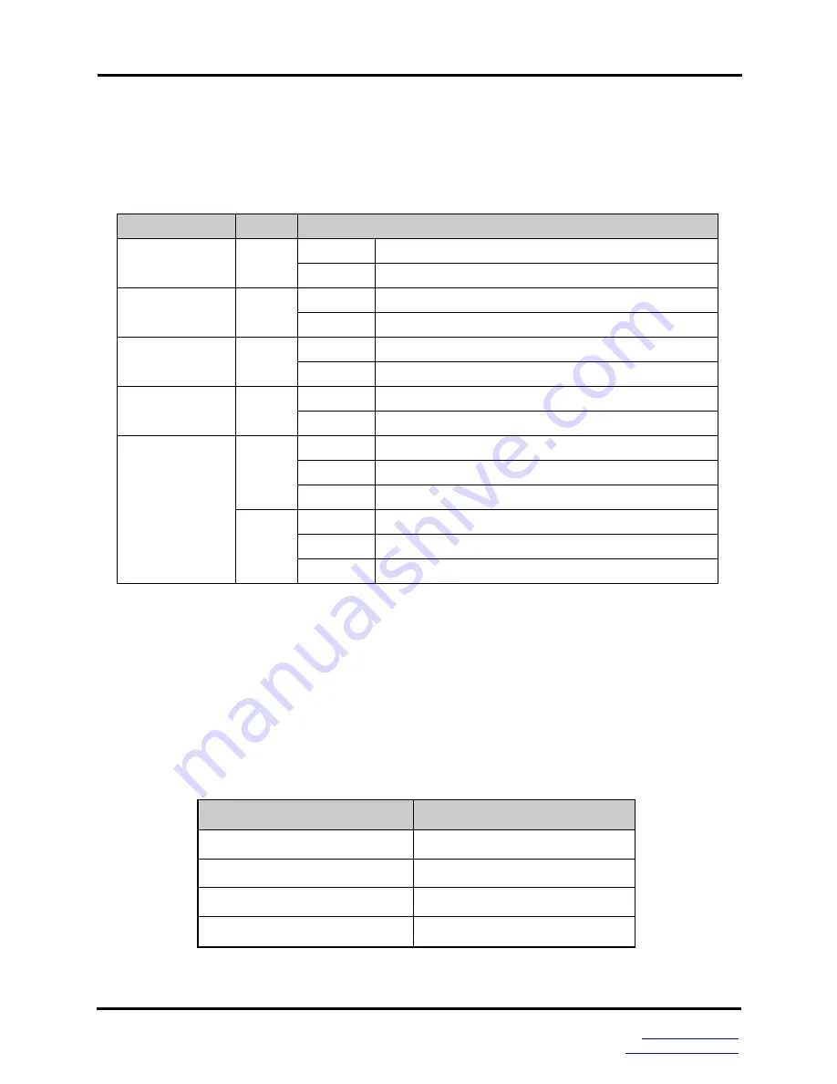
Below is a table that explains the status of each of the power and network status LED’s
found on the front panel of the EIRP305-T.
LED
Color
Description
P1
Green
On
Power input 1 is active
Off
Power input 1 is inactive
P2
Green
On
Power input 2 is active
Off
Power input 2 is inactive
Fault
Red
On
Power input 1 or 2 has failed
Off
Power input 1 and 2 are both functional, or no power is
FWD (1 to 4)
Green
On
The port is supplying power to the connected device
Off
No device attached or no power being supplied
1 to 5 (RJ-45)
Green
(Upper
LED)
On
Connected to network
Flashing
Networking is active
Off
Not connected to network
Yellow
(Lower
LED)
On
Full-duplex link
Flashing
Collision occurs
Off
Half-duplex link or link down
Ports
RJ-45 ports
: The RJ-45 ports auto-sense for 10 or 100 Mbps device connections. The
auto MDI/MDIX feature allows connections to switches, workstation and other equipment
without changing straight through or crossover cabling. The charts below show the cable
pin assignments for straight through and crossover cables.
RJ-45 Pin Assignments
Pin Number
Assignment
1
Tx+
2
Tx-
3
Rx+
6
Rx-
Note
“+” and “-” signs represent the polarity of each wire pair.


