ENGLISH
15 / 44
0006160077_201802
ELECTRICAL CONNECTIONS
• It is advisable to make all connections with flexible electric wire.
• Electrical lines must be kept away from hot parts.
• The burner installation is allowed only in environments with
pollution degree 2 as indicated in annex M of the EN 60335-
1:2008-07 regulation.
• Make sure that the electric line to which the unit will be connected
has frequency and voltage ratings suitable for the burner.
• The three-phase or single-phase power supply line must have
a switch with fuses. The standards also require a switch on the
burner's power line located outside the boiler room where it can be
accessed easily.
• The main line, the relevant switch with fuses and the possible
limiter must be suitable to support the maximum current absorbed
by the burner.
• The mains supply connection requires an omnipolar switch with a
contact opening gap equal to or greater than 3 mm in accordance
with current safety regulations.
• Refer to the wiring diagram for electrical connections (line and
thermostats).
• Unsheathe the external insulating cover of the power cable to the
necessary extent for the connection, thus avoiding the wire from
coming into contact with metal parts.
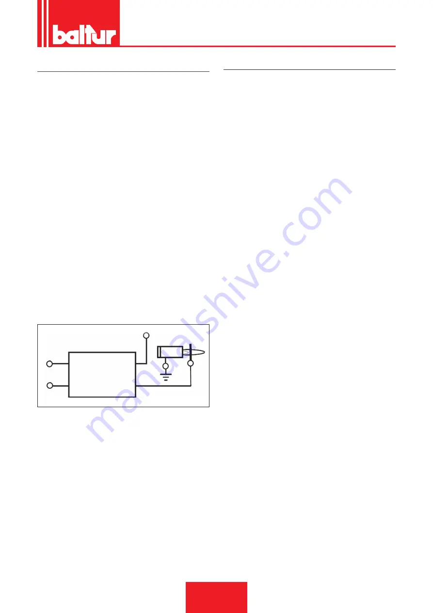
• In case of unbalanced 230V phase-phase mains supply systems,
the voltage between the flame detector electrode and earth might
not be enough to ensure the correct operation of the burner. The
problem is eliminated using the isolation transformer type AR1
code 0005020028 which must be connected as shown in the
following diagram.
Ph
Ph 230
ION IN
ION PROBE
AR 1
ION
L (1)
IN (2)
tensione_elettrodi
AUXILIARY PUMP
In some cases (excessive distance or differences in level) the system
must be implemented with a "loop" supply circuit with an auxiliary
pump, avoiding to connect the burner pump directly to the tank.
In this case, the auxiliary pump can be started when the burner starts
and stopped when it stops.
The electrical connection of the auxiliary pump is made by connecting
the coil (230V), which controls the pump remote control switch, to
terminals “N” (input terminal board of the equipment) and “L1”
(downstream the motor remote control switch).
It is important to comply strictly with the previsions set forth here
below:
• The auxiliary pump must be installed as close as possible to the
liquid to be sucked.
• The head must be suitable for the relative plant.
• We recommend a flow rate that is at least equal to the flow rate of
the burner pump.
• Connection pipes should be sized to cope with the delivery rate of
the auxiliary pump.
• Absolutely avoid electrically connecting the auxiliary pump directly
to the contactor of the burner.
Summary of Contents for 56710010
Page 2: ......
Page 23: ...ITALIANO 21 44 0006160077_201802 ...
Page 24: ...ITALIANO 22 44 0006160077_201802 ...
Page 25: ...ITALIANO 23 44 0006160077_201802 ...
Page 26: ...ITALIANO 24 44 0006160077_201802 ...
Page 27: ...ITALIANO 25 44 0006160077_201802 ...
Page 28: ...ITALIANO 26 44 0006160077_201802 ...
Page 29: ...ITALIANO 27 44 0006160077_201802 ...
Page 41: ...ITALIANO 39 44 0006160077_201802 SCHEMI ELETTRICI ...
Page 42: ...ITALIANO 40 44 0006160077_201802 ...
Page 43: ...ITALIANO 41 44 0006160077_201802 ...
Page 44: ...ITALIANO 42 44 0006160077_201802 ...
Page 45: ...ITALIANO 43 44 0006160077_201802 ...
Page 67: ...ENGLISH 21 44 0006160077_201802 ...
Page 68: ...ENGLISH 22 44 0006160077_201802 ...
Page 69: ...ENGLISH 23 44 0006160077_201802 ...
Page 70: ...ENGLISH 24 44 0006160077_201802 ...
Page 71: ...ENGLISH 25 44 0006160077_201802 ...
Page 72: ...ENGLISH 26 44 0006160077_201802 ...
Page 73: ...ENGLISH 27 44 0006160077_201802 ...
Page 85: ...ENGLISH 39 44 0006160077_201802 WIRING DIAGRAMS ...
Page 86: ...ENGLISH 40 44 0006160077_201802 ...
Page 87: ...ENGLISH 41 44 0006160077_201802 ...
Page 88: ...ENGLISH 42 44 0006160077_201802 ...
Page 89: ...ENGLISH 43 44 0006160077_201802 ...
Page 91: ......


