


ITALIAN
SUMMARY
Warnings for use in safety conditions .....................................................................................................................................................................2
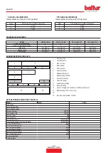
Technical specifications
..........................................................................................................................................................................................5
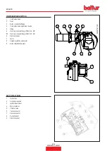
Standard accessories .......................................................................................................................................................................................6
Burner identification plate
.................................................................................................................................................................................6
Data recorded during first start-up
....................................................................................................................................................................6
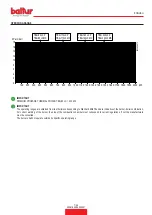
Operating range ...............................................................................................................................................................................................7
Component description ....................................................................................................................................................................................8
Electrical panel .................................................................................................................................................................................................8
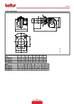
Overall dimensions ...........................................................................................................................................................................................9
Design characteristics ....................................................................................................................................................................................10
Technical functional characteristics ................................................................................................................................................................10
Supply line ......................................................................................................................................................................................................11
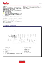
Gas train block diagram
........................................................................................................................................................................................11
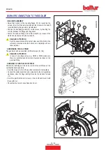
Burner connection to the boiler
.............................................................................................................................................................................12
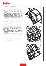
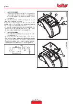
Electrical connections ...........................................................................................................................................................................................13
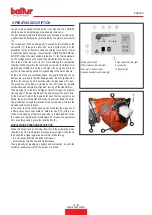
Operating description ...........................................................................................................................................................................................15
Modulation operation description ...................................................................................................................................................................15
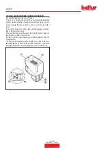
“VPS 504” valve tightness control (if present) ................................................................................................................................................16
Air regulation on the combustion head
...........................................................................................................................................................17
Starting up and regulation ....................................................................................................................................................................................17
Ionisation current measurement .....................................................................................................................................................................20
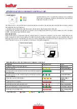
Control and command equipment LME... .............................................................................................................................................................21
Ionization probe/electrode adjustment diagram
.............................................................................................................................................25
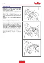
Maintenance .........................................................................................................................................................................................................26
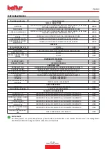
maintenance time ...........................................................................................................................................................................................27
Expected lifespan
...........................................................................................................................................................................................28
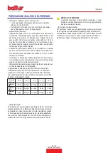
Specifications for propane use
.............................................................................................................................................................................29
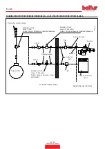
Block diagram illustrating the principle of L.P.G. pressure reduction in two stages for burner or boiler
.........................................................30
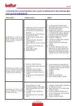
Instructions for determining the cause leading to irregularities in the operation and their elimination .................................................................31
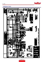
Wiring diagrams ....................................................................................................................................................................................................32
ENGLISH
1 / 34
0006160254_202001
Summary of Contents for TBG 80 LX MC
Page 2: ......
Page 34: ...SCHEMI ELETTRICI ITALIANO 32 34 0006160254_202001...
Page 36: ...ITALIANO 34 34 0006160254_202001...
Page 68: ...WIRING DIAGRAMS ENGLISH 32 34 0006160254_202001...
Page 70: ...ENGLISH 34 34 0006160254_202001...
Page 71: ......


