4 Installation
Warning:
The instructions on
(Section
) related to the 3D stereo camera must be read and
understood prior to installation.
4.1 Mounting
The 3D stereo camera is intended to be mounted on a wall or ceiling above the target area. It is not intended
to be used in dynamic applications mounted to a robot wrist. It is the customer’s responsibility to provide an
adequate mounting bracket.
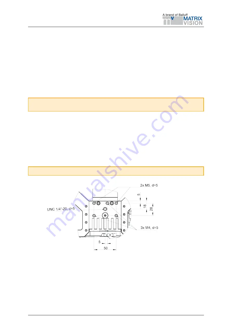
For mounting, the 3D stereo camera provides an M4 and M5 thread pattern on its top and bottom sides (see
). A medium-strength thread-locker or Tuflok® screws must be used to protect against vibrations. M5
screws must be tightened to 4.0 Nm, M4 screws must be tightened to 3.3 Nm.
Warning:
The 3D stereo camera cannot be mounted on the end-effector of a robot.
Fig. 4.1: Mounting of the 3D stereo camera
Only the surface containing the thread pattern must be in contact with the mounting bracket, all other surfaces
must remain free. At least 10 cm clearance must be provided behind the 3D stereo camera to facilitate
adequate air flow for cooling.
MATRIX VISION GmbH
Manual: BVS 3D-RV1
18
Rev: 1.0
Status: Nov 14, 2022


