3.6. Coordinate frames
Warning:
Proper cable management is mandatory. Cabling must always be secured to the 3D stereo
camera mount with a strain-relief clamp so that no forces due to cable movements are exerted on the 3D
stereo camera’s M12 connectors. Enough slack needs to be provided to allow for full range of movement
of the camera without straining the cable. The cable’s minimum bend radius (i.e.
𝑅
𝑚𝑖𝑛
= 15
𝑑
) needs to
be observed.
Pin assignments for the power connector are given in
Table 3.6: Pin assignments for the power connector
Pin
Cable Color
Designation
Details
1
White
nc
2
Brown
Power +24 V
2 A @ 24 V
3
Green
nc
4
Yellow
nc
5
Grey
GPIO Vcc
5-24 V, 50 mA max.
6
Pink
GPIO Out 1
Projector exposure signal
7
Blue
Power GND
8
Red
GPIO Out 2
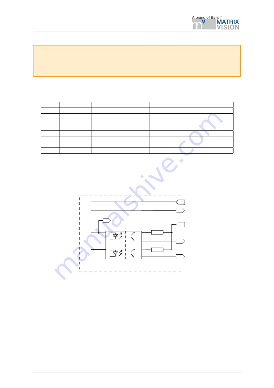
GPIOs are decoupled by photocouplers.
GPIO Out 1
by default provides an exposure sync signal with a
logic high level for the duration of the image exposure. Pins of unused GPIOs should be left floating. GPIO
circuitry and specifications are shown in
GPIO Out:
Uext = 5VDC to 29 VDC
Iout = max 50 mA
GPIO_Power_Vcc
GPIO_Out1_Robot
GPIO_Out2_Robot
GND
Power IN
75
75
3D Stereo Camera
Projector_Exposure
to Robot Controller
Fig. 3.4: GPIO circuitry and specifications
3.6 Coordinate frames
The 3D stereo camera’s coordinate-frame origin is defined as the exit pupil of the left camera lens. This frame
is called camera coordinate frame. It is shown in
MATRIX VISION GmbH
Manual: BVS 3D-RV1
16
Rev: 1.0
Status: Nov 14, 2022


