background image

12

english

6.1 

Accuracy

The specifications are typical values for BTL7-V50T... at 

24 V DC and room temperature, with a nominal length of 

500 mm in conjunction with the BTL5-P-3800-2, 

BTL5-P-4500-1, BTL5-P-5500-2

1)

, BTL6-A-3800-2

1)

BTL6-A-3801-2

1)

, BTL5-F-2814-1S, BTL5-T-2814-1S, 

BTL5-M-2814-1S or BTL5-N-2814-1S.

The BTL is fully operational immediately, with full accuracy 

after warm-up.

For special versions, other technical data may 

apply.

Special versions are indicated by the suffix -SA 

on the part label.

Position resolution

1 µm

Non-linearity with a constant distance 

between the magnet and profile:

  Nominal length 

 5500 mm

  Nominal length 

>

 5500 mm

±30 µm

±0.02 % FS

Hysteresis

 ±10 µm

Repeat accuracy

 ±5 µm  

(typ. ±2.5 µm)

Temperature coefficient

2) 

≤ 

18 ppm/K

Velocity resolution

0.1 mm/s

Min. detectable velocity

1 mm/s

Max. detectable velocity

10 m/s

6.2 

Ambient conditions

3)

Operating temperature

40°C to +85°C

Storage temperature

40°C to +100°C

Relative humidity

< 90%, non-condensing

Shock rating  

per EN 60068-2-27

4)

150 g/6 ms

Continuous shock  

per EN 60068-2-29

4)

150 g/2 ms

Vibration  

per EN 60068-2-6

4) 


20 g, 10 to 2000 Hz

Degree of protection per 

IEC 60529

Connector C003 (when 

attached)

IP 67

6.3 

Supply voltage (external)

Voltage, stabilized

5)

10 to 30 V DC

Ripple

 0.5 V

SS

Current draw (at 24 V DC)

 120 mA up to 1524 mm

 160 mA from 1525 mm

Inrush current

 500 mA/10 ms

Reverse polarity protection

Up to 36 V

Overvoltage protection

Up to 36 V

Dielectric strength  

(GND to housing)

500 V AC

6.4 

Output

Short-circuit resistance

Signal cable to GND

6.5 

Dimensions, weights

Housing height

36.8 mm

Nominal length

50 to 7620 mm

Weight (depends on length)

Approx. 1.4 kg/m

Housing material

Anodized aluminum

6.6 

Maximum sampling rate f

max

At nominal length

 0050 to 0250 mm

 0251 to 0600 mm

 0601 to 1300 mm

  1301 to 2700 mm

  2701 to 5500 mm

  5501 to 7600 mm

  > 7601 mm

780 Hz

710 Hz

600 Hz

460 Hz

245 Hz

180 Hz

170 Hz

1)

 In the position range 0 to 20 mm, the specified linearity limit can be 

exceeded by ±100 µm.

2)

 Nominal length = 500 mm, magnet in the middle of the measuring range

3)

 For 

: Use in enclosed spaces and up to a height of 2000 m above sea 

level.

4)

 Individual specifications as per Balluff factory standard

5)

 For 

: The transducer must be externally connected via a limited-

energy circuit as defined in UL 61010-1, a low-power source as defined in 
UL 60950-1, or a class 2 power supply as defined in UL 1310 or 
UL 1585.

Technical data

BTL7-V50T-M _ _ _ _ -P-C003

Micropulse Transducer in a Profile Housing

Summary of Contents for BTL7-V50T-M-P-C003 Series

Page 1: ...BTL7 V50T M_ _ _ _ P C003 Betriebsanleitung deutsch...

Page 2: ...www balluff com...

Page 3: ...10 4 4 1 Steckverbinder BTL7 C003 10 4 5 Schirmung und Kabelverlegung 10 5 Inbetriebnahme 11 5 1 System in Betrieb nehmen 11 5 2 Hinweise zum Betrieb 11 6 Technische Daten 12 6 1 Genauigkeit 12 6 2 Um...

Page 4: ...n und Kennzeichnungen UL Zulassung File No E227256 Zertifiziert nach Conformance Class A B und C Mit dem CE Zeichen best tigen wir dass unsere Produkte den Anforderungen der EU Richtlinie 2004 108 EG...

Page 5: ...sma nahmen treffen kann Der Betreiber hat die Verantwortung dass die rtlich geltenden Sicherheitsvorschriften eingehalten werden Insbesondere muss der Betreiber Ma nahmen treffen dass bei einem Defekt...

Page 6: ...t siehe www profibus com Der Wegaufnehmer ist in der Lage bis zu 16 Positionsge ber zu detektieren und zu verarbeiten Die maximale Anzahl der Positionsgeber ist abh ngig von der Nenn l nge Zu jedem Po...

Page 7: ...altet Blinken1 An Busverbindung Link vorhanden jedoch befindet sich der Sensor nicht im zyklischen Datenaustausch Startup des Sensors ist im Gange die Parametrierung ist allerdings noch nicht abgeschl...

Page 8: ...hmer mit den Befestigungsschrauben auf dem Untergrund fixieren Schrauben in den Klammern mit max 2 Nm festziehen 3 Postionsgeber Zubeh r einbauen Der Wegaufnehmer Micropulse in Profilbau weise eignet...

Page 9: ...rsatz C BTL5 P 3800 2 0 1 4 mm 2 mm BTL5 P 5500 2 5 15 mm 15 mm BTL5 P 4500 1 0 1 2 mm 2 mm BTL6 A 3800 2 4 8 mm2 2 mm BTL6 A 3801 2 4 8 mm2 2 mm 1 Der gew hlte Abstand sollte ber die gesamte Messl ng...

Page 10: ...en Vertr glich keit EMV sind folgende Hinweise zu beachten Wegaufnehmer und Steuerung mit einem geschirmten Kabel verbinden Schirmung Geflecht aus Kupfer Einzeldr hten Bede ckung mindestens 85 Stecker...

Page 11: ...es Anlagen oder Systemher stellers beachten 1 Anschl sse auf festen Sitz und richtige Polung pr fen Besch digte Anschl sse tauschen 2 System einschalten 3 Messwerte und einstellbare Parameter pr fen u...

Page 12: ...10 bis 2000 Hz Schutzart nach IEC 60529 Stecker C003 in ver schraubtem Zustand IP 67 6 3 Spannungsversorgung extern Spannung stabilisiert5 10 30 V DC Restwelligkeit 0 5 VSS Stromaufnahme bei 24 V DC 1...

Page 13: ...BTL5 F 2814 1S Gewicht ca 28 g Geh use Aluminium eloxiert Gleitfl che Kunststoff BTL5 T 2814 1S 16 5 11 5 28 22 40 M5x10 Bild 7 3 Einbauma e Positionsgeber BTL5 T 2814 1S Gewicht ca 28 g Geh use Alum...

Page 14: ...Geh use Kunststoff BTL6 A 3801 2 28 16 21 37 6 4 2 18 13 Bild 7 8 Einbauma e Positionsgeber BTL6 A 3801 2 Gewicht ca 25 g Geh use Kunststoff BTL5 P 4500 1 16 5 45 25 28 15 4 2 25 7 5 M5x8 40 Bild 7 9...

Page 15: ...tenkabel konfektioniert mit M12 Stecker Steckverbinder gerade umspritzt konfektioniert Stecker M12 I Stecker M12 II 4 polig I II 48 5 48 5 M12x1 14 5 M12x1 14 5 max 7 Bild 7 12 Steckerverbinder gerade...

Page 16: ...Bild 7 14 Steckerverbinder Stecker gerade Typ Bestellcode BCC M474 0000 2D 000 51X475 000 BCC03WZ 7 4 6 Datenstecker gewinkelt frei konfektionierbar 20 M12x1 64 42 18 18 Bild 7 15 Steckerverbinder Ste...

Page 17: ...0 bis 30 V DC Kennliniencharakteristik 0 konfigurierbar Ethernet Schnittstellentyp T PROFINET Nennl nge 4 stellig M0500 metrische Angabe in mm Nennl nge 500 mm M0050 M7620 Bauform P Profilgeh use Elek...

Page 18: ...9 0 35433071 10 0 393700787 Tab 9 1 Umrechnungstabelle mm inch 1 inch 25 4 mm inch mm 1 25 4 2 50 8 3 76 2 4 101 6 5 127 6 152 4 7 177 8 8 203 2 9 228 6 10 254 Tab 9 2 Umrechnungstabelle inch mm 9 An...

Page 19: ...lluff GmbH Schurwaldstrasse 9 73765 Neuhausen a d F Phone 49 7158 173 370 Fax 49 7158 173 691 service balluff de US Service Center USA Balluff Inc 8125 Holton Drive Florence KY 41042 Phone 859 727 220...

Page 20: ...BTL7 V50T M_ _ _ _ P C003 User s Guide english...

Page 21: ...www balluff com...

Page 22: ...ts 9 4 4 Electrical connection 10 4 4 1 Connector BTL7 C003 10 4 5 Shielding and cable routing 10 5 Startup 11 5 1 Starting up the system 11 5 2 Operating notes 11 6 Technical data 12 6 1 Accuracy 12...

Page 23: ...fied in accordance with Conformance Class A B and C The CE Mark verifies that our products meet the requirements of EU Directive 2004 108 EC EMC Directive The transducer meets the requirements of the...

Page 24: ...egulations pertaining to the work to be done The operator is responsible for ensuring that local safety regulations are observed In particular the operator must take steps to ensure that a defect in t...

Page 25: ...fibus com The transducer can detect and process up to 16 magnets The maximum number of magnets depends on the nominal length The position and velocity of each magnet can be output Implementation is ba...

Page 26: ...is switched off Flashing1 On Bus connection link available but the sensor is not involved in cyclic data exchange Sensor is starting up but parameterization has not yet been completed Sensor has been...

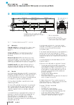
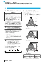
Page 27: ...mounting clamps 2 Attach transducer to the base using mounting screws tighten screws in the clamps with max 2 Nm 3 Insert magnet accessories The micropulse transducer in profile housing is suitable bo...

Page 28: ...mm 2 mm BTL5 P 5500 2 5 to 15 mm 15 mm BTL5 P 4500 1 0 1 to 2 mm 2 mm BTL6 A 3800 2 4 to 8 mm2 2 mm BTL6 A 3801 2 4 to 8 mm2 2 mm 1 The selected distance should stay constant over the entire measurin...

Page 29: ...ng Connect transducer and controller using a shielded cable Shielding Braided copper shield with minimum 85 coverage Connector version Shield is internally connected to connector housing Magnetic fiel...

Page 30: ...or system manufacturer 1 Check connections for tightness and correct polarity Replace damaged connections 2 Turn on the system 3 Check measured values and adjustable parameters and readjust the transd...

Page 31: ...Connector C003 when attached IP 67 6 3 Supply voltage external Voltage stabilized5 10 to 30 V DC Ripple 0 5 VSS Current draw at 24 V DC 120 mA up to 1524 mm 160 mA from 1525 mm Inrush current 500 mA...

Page 32: ...S magnet Weight Approx 28 g Housing Anodized aluminum Slide surface Plastic BTL5 T 2814 1S 16 5 11 5 28 22 40 M5x10 Fig 7 3 Installation dimensions of BTL5 T 2814 1S magnet Weight Approx 28 g Housing...

Page 33: ...Approx 30 g Housing Plastic BTL6 A 3801 2 28 16 21 37 6 4 2 18 13 Fig 7 8 Installation dimensions of BTL6 A 3801 2 magnet Weight Approx 25 g Housing Plastic BTL5 P 4500 1 16 5 45 25 28 15 4 2 25 7 5 M...

Page 34: ...ble preassembled with M12 plug Straight connector molded preassembled M12 plug I M12 plug II 4 pin I II 48 5 48 5 M12x1 14 5 M12x1 14 5 max 7 Fig 7 12 Straight straight connector Type Ordering code BC...

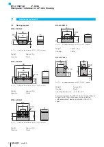
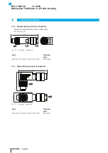
Page 35: ...Fig 7 14 Connector straight plug Type Ordering code BCC M474 0000 2D 000 51X475 000 BCC03WZ 7 4 6 Angled data plug freely configurable 20 M12x1 64 42 18 18 Fig 7 15 Connector angled plug Type Orderin...

Page 36: ...to 30 V DC Output gradient 0 Configurable Ethernet interface type T PROFINET Nominal length 4 digit M0500 Metric specification in mm nominal length 500 mm M0050 to M7620 Construction P profile housing...

Page 37: ...0 35433071 10 0 393700787 Tab 9 1 Conversion table mm to inches 1 inch 25 4 mm inch mm 1 25 4 2 50 8 3 76 2 4 101 6 5 127 6 152 4 7 177 8 8 203 2 9 228 6 10 254 Tab 9 2 Conversion table inches to mm...

Page 38: ...Drive Florence KY 41042 Phone 859 727 2200 Toll free 1 800 543 8390 Fax 859 727 4823 technicalsupport balluff com CN Service Center China Balluff Shanghai trading Co ltd Room 1006 Pujian Rd 145 Shangh...

Page 39: ...BTL7 V50T M_ _ _ _ P C003 Manual de instrucciones espa ol...

Page 40: ...www balluff com...

Page 41: ...l ctrica 10 4 4 1 Conector BTL7 C003 10 4 5 Blindaje y tendido de cables 10 5 Puesta en servicio 11 5 1 Puesta en servicio del sistema 11 5 2 Indicaciones sobre el servicio 11 6 Datos t cnicos 12 6 1...

Page 42: ...mance Class A B y C Con el marcado CE confirmamos que nuestros productos cumplen con los requerimientos de la directiva de la UE 2004 108 CE directiva CEM El transductor de desplazamiento cumple con l...

Page 43: ...guridad adecuadas El explotador es responsable de respetar las normas de seguridad locales vigentes En particular el explotador debe adoptar medidas destinadas a evitar peligros para las personas y da...

Page 44: ...a f sica de Ethernet v ase www profibus com El transductor de desplazamiento es capaz de detectar y procesar hasta 16 sensores de posici n El n mero m ximo de sensores de posici n depende de la longit...

Page 45: ...t localizable o est apagado Parpadeo1 ON Bus conectado enlace pero el sensor no se encuentra en intercambio de datos c clico El arranque del sensor est en marcha pero la parametrizaci n a n no ha conc...

Page 46: ...s de fijaci n en la base apriete los tornillos en las pinzas con m x 2 Nm 3 Monte el sensor de posici n accesorio El transductor de desplazamiento Micropulse en construcci n perfilada es apto tanto pa...

Page 47: ...o C BTL5 P 3800 2 0 1 4 mm 2 mm BTL5 P 5500 2 5 15 mm 15 mm BTL5 P 4500 1 0 1 2 mm 2 mm BTL6 A 3800 2 4 8 mm2 2 mm BTL6 A 3801 2 4 8 mm2 2 mm 1 La distancia seleccionada debe permanecer constante en t...

Page 48: ...cte el transductor de desplazamiento y el control con un cable blindado Blindaje malla de hilos individuales de cobre cobertura m nima del 85 Ejecuci n de conector conecte superficialmente el blindaje...

Page 49: ...iones est n asentadas firmemente y tengan la polaridad correcta Sustituya las conexiones da adas 2 Conecte el sistema 3 Compruebe los valores de medici n y los par metros ajustables y en caso necesari...

Page 50: ...ci n de tensi n externa Tensi n estabilizada5 10 30 V DC Ondulaci n residual 0 5 VSS Consumo de corriente con 24 V DC 120 mA hasta 1524 mm 160 mA de 1525 mm Corriente de pico 500 mA 10 ms Protecci n c...

Page 51: ...a Aluminio anodizado Superficie de deslizamiento Material sint tico BTL5 T 2814 1S 16 5 11 5 28 22 40 M5x10 Fig 7 3 Medidas de montaje del sensor de posici n BTL5 T 2814 1S Peso Aprox 28 g Carcasa Alu...

Page 52: ...ico BTL6 A 3801 2 28 16 21 37 6 4 2 18 13 Fig 7 8 Medidas de montaje del sensor de posici n BTL6 A 3801 2 Peso Aprox 25 g Carcasa Material sint tico BTL5 P 4500 1 16 5 45 25 28 15 4 2 25 7 5 M5x8 40 F...

Page 53: ...feccionado con conector M12 Conector recto recubierto confeccionado Conector macho M12 I conector macho M12 II 4 polos I II 48 5 48 5 M12x1 14 5 M12x1 14 5 max 7 Fig 7 12 Conector recto recto Modelo C...

Page 54: ...ector con macho recto Modelo C digo de pedido BCC M474 0000 2D 000 51X475 000 BCC03WZ 7 4 6 Conector de datos acodado libremente confeccionable 20 M12x1 64 42 18 18 Fig 7 15 Conector con macho acodado...

Page 55: ...aracter sticas de la curva 0 Configurable Tipo de interfaz Ethernet T PROFINET Longitud nominal 4 cifras M0500 indicaci n m trica en mm longitud nominal 500 mm M0050 M7620 Forma constructiva P carcasa...

Page 56: ...7 Tab 9 1 Tabla de conversi n mm pulgadas 1 pulgada 25 4 mm pulgadas mm 1 25 4 2 50 8 3 76 2 4 101 6 5 127 6 152 4 7 177 8 8 203 2 9 228 6 10 254 Tab 9 2 Tabla de conversi n pulgadas mm 9 Anexo 9 2 Pl...

Page 57: ...alluff Inc 8125 Holton Drive Florence KY 41042 Phone 859 727 2200 Toll free 1 800 543 8390 Fax 859 727 4823 technicalsupport balluff com CN Service Center China Balluff Shanghai trading Co ltd Room 10...

Page 58: ...BTL7 V50T M_ _ _ _ P C003 Notice d utilisation fran ais...

Page 59: ...www balluff com...

Page 60: ...lectrique 10 4 4 1 Connecteur BTL7 C003 10 4 5 Blindage et pose des c bles 10 5 Mise en service 11 5 1 Mise en service du syst me 11 5 2 Conseils d utilisation 11 6 Caract ristiques techniques 12 6 1...

Page 61: ...tion selon la classe de conformit A B et C Avec le symbole CE nous certifions que nos produits r pondent aux exigences de la directive europ enne 2004 108 UE directive CEM Le capteur de d placement sa...

Page 62: ...s mesures de s curit ad quates Il est de la responsabilit de l exploitant de veiller ce que les dispositions locales concernant la s curit soient respect es L exploitant doit en particulier prendre le...

Page 63: ...capable de d tecter et g rer jusqu 16 capteurs de position Le nombre maximal de capteurs de position d pend de la longueur nominale Il est possible de d terminer la position et la v locit de chaque ca...

Page 64: ...connect Ma tre inaccessible ou d sactiv Clignotante1 Allum e Connexion bus link disponible mais le capteur ne trouve pas en change cyclique de donn es D marrage du capteur en cours mais le param trag...

Page 65: ...a base vissage de max 2 Nm dans les brides 3 Monter le capteur de position accessoire Le capteur de d placement Micropulse construction profil e convient aussi bien aux capteurs de position libres c e...

Page 66: ...5 15 mm 15 mm BTL5 P 4500 1 0 1 2 mm 2 mm BTL6 A 3800 2 4 8 mm2 2 mm BTL6 A 3801 2 4 8 mm2 2 mm 1 La distance choisie doit rester constante sur toute la longueur de mesure 2 Pour un r sultat de mesur...

Page 67: ...spect es Relier le capteur de d placement et la commande avec un c ble blind Blindage tresse de fils de cuivre couverture minimum 85 Mod le de connecteur relier plat le blindage du connecteur au bo ti...

Page 68: ...du fabricant doivent tre respect es 1 V rifier la fixation et la polarit des raccordements Remplacer les raccordements endommag s 2 Mettre le syst me en marche 3 V rifier les valeurs mesur es et les p...

Page 69: ...n lectrique externe Tension stabilis e5 10 30 V CC Ondulation r siduelle 0 5 VSS Consommation de courant 24 V CC 120 mA jusqu 1524 mm 160 mA partir de 1525 mm Courant de cr te au d marrage 500 mA 10 m...

Page 70: ...5 F 2814 1S Poids Env 28 g Bo tier Aluminium anodis Surface de glissement Plastique BTL5 T 2814 1S 16 5 11 5 28 22 40 M5x10 Fig 7 3 Dimensions de montage du capteur de position BTL5 T 2814 1S Poids En...

Page 71: ...tier Plastique BTL6 A 3801 2 28 16 21 37 6 4 2 18 13 Fig 7 8 Dimensions de montage du capteur de position BTL6 A 3801 2 Poids Env 25 g Bo tier Plastique BTL5 P 4500 1 16 5 45 25 28 15 4 2 25 7 5 M5x8...

Page 72: ...s confectionn avec connecteur M12 Connecteur droit extrud confectionn Connecteur M12 I connecteur M12 II 4 p les I II 48 5 48 5 M12x1 14 5 M12x1 14 5 max 7 Fig 7 12 Connecteur droit droit Type Symboli...

Page 73: ...ise m le droite Type Symbolisation commerciale BCC M474 0000 2D 000 51X475 000 BCC03WZ 7 4 6 Connecteur de donn es coud assembler 20 M12x1 64 42 18 18 Fig 7 15 Connecteur prise m le coud e Type Symbol...

Page 74: ...ct ristique des courbes 0 configurable Type d interface Ethernet T PROFINET Longueur nominale 4 chiffres M0500 donn e m trique en mm longueur nominale 500 mm M0050 M7620 Forme de construction P bo tie...

Page 75: ...0 393700787 Tab 9 1 Conversion mm pouce 1 pouce 25 4 mm pouce mm 1 25 4 2 50 8 3 76 2 4 101 6 5 127 6 152 4 7 177 8 8 203 2 9 228 6 10 254 Tab 9 2 Conversion pouce mm 9 Annexe 9 2 Plaque signal tique...

Page 76: ...f Inc 8125 Holton Drive Florence KY 41042 Phone 859 727 2200 Toll free 1 800 543 8390 Fax 859 727 4823 technicalsupport balluff com CN Service Center China Balluff Shanghai trading Co ltd Room 1006 Pu...

Page 77: ...BTL7 V50T M_ _ _ _ P C003 Manuale d uso Italiano...

Page 78: ...www balluff com...

Page 79: ...BTL7 C003 10 4 5 Schermatura e posa dei cavi 10 5 Messa in funzione 11 5 1 Messa in funzione del sistema 11 5 2 Avvertenze per il funzionamento 11 6 Dati tecnici 12 6 1 Precisione 12 6 2 Condizioni am...

Page 80: ...E227256 Certificazione secondo Conformance Class A B e C Il marchio CE la conferma che i nostri prodotti sono conformi ai requisiti della Direttiva UE 2004 108 CE direttiva CEM Il trasduttore di posi...

Page 81: ...ericoli e di adottare misure di sicurezza adeguate Il gestore ha la responsabilit di far rispettare le norme di sicurezza vigenti localmente In particolare il gestore deve adottare provvedimenti tali...

Page 82: ...a bus industriale che si basa sullo strato fisico di Ethernets vedere www profibus com Il trasduttore di posizione in grado di rilevare ed elaborare fino a 16 datori di posizione Il numero massimo di...

Page 83: ...pento Lampeggio1 Acceso Collegamento bus link presente tuttavia il sensore non si trova in scambio dati ciclico Avvio del sensore in corso mentre la parametrizzazione non ancora completata Sensore con...

Page 84: ...la base con le viti di fissaggio serrare le viti nelle staffe o nelle fascette con max 2 Nm 3 Montare il datore di posizione accessorio Il trasduttore di posizione Micropulse in corpo profilato idoneo...

Page 85: ...istanza B1 Sfasamento C BTL5 P 3800 2 0 1 4 mm 2 mm BTL5 P 5500 2 5 15 mm 15 mm BTL5 P 4500 1 0 1 2 mm 2 mm BTL6 A 3800 2 4 8 mm2 2 mm BTL6 A 3801 2 4 8 mm2 2 mm 1 La distanza selezionata dovrebbe rim...

Page 86: ...gare il trasduttore di posizione e l unit di controllo con un cavo schermato Schermatura maglia di singoli fili di rame copertura minima 85 Versione con connettore collegare la schermatura nel connett...

Page 87: ...ollare che i collegamenti siano fissati saldamente e che la loro polarit sia corretta Sostituire i collegamenti danneggiati 2 Attivare il sistema 3 Controllare i valori misurati e i parametri regolabi...

Page 88: ...entazione esterna Tensione stabilizzata5 10 30 V DC Ondulazione residua 0 5 VSS Corrente assorbita con 24 V DC 120 mA fino a 1524 mm 160 mA da 1525 mm Corrente massima di avviamento 500 mA 10 ms Prote...

Page 89: ...Supporto alluminio anodizzato Superficie di scorrimento materiale plastico BTL5 T 2814 1S 16 5 11 5 28 22 40 M5x10 Fig 7 3 Dimensioni di ingombro datore di posizione BTL5 T 2814 1S Peso ca 28 g Suppo...

Page 90: ...upporto materiale plastico BTL6 A 3801 2 28 16 21 37 6 4 2 18 13 Fig 7 8 Dimensioni di ingombro datore di posizione BTL6 A 3801 2 Peso ca 25 g Supporto materiale plastico BTL5 P 4500 1 16 5 45 25 28 1...

Page 91: ...ezionato con connettore M12 Connettore diritto incorporato confezionato Connettore M12 I connettore M12 II 4 poli I II 48 5 48 5 M12x1 14 5 M12x1 14 5 max 7 Fig 7 12 Connettore a spina diritto diritto...

Page 92: ...4 Connettore connettore diritto Tipo Codice d ordine BCC M474 0000 2D 000 51X475 000 BCC03WZ 7 4 6 Connettore dati ad angolo confezionabile liberamente 20 M12x1 64 42 18 18 Fig 7 15 Connettore connett...

Page 93: ...0 a 30 V DC Curva caratteristica 0 configurabile Tipo interfaccia Ethernet T PROFINET Lunghezza nominale a 4 cifre M0500 indicazione metrica in mm lunghezza nominale 500 mm M0050 M7620 Forma costrutti...

Page 94: ...b 9 1 Tabella di conversione mm pollici 1 pollice 25 4 mm pollici mm 1 25 4 2 50 8 3 76 2 4 101 6 5 127 6 152 4 7 177 8 8 203 2 9 228 6 10 254 Tab 9 2 Tabella di conversione pollici mm 9 Appendice 9 2...

Page 95: ...Drive Florence KY 41042 Phone 859 727 2200 Toll free 1 800 543 8390 Fax 859 727 4823 technicalsupport balluff com CN Service Center China Balluff Shanghai trading Co ltd Room 1006 Pujian Rd 145 Shang...

Reviews: