16
english
Ignition protection
“ec” and “tb”
6
Calibration procedure (continued)
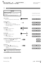
6.3.2 Adjusting
The detailed procedure for adjusting is
described on page 18 ff.
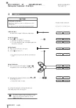
The factory set null point and end point is replaced by a
new start point and end point and the associated output
values can be adjusted. The start and end values can be
adjusted as you like up to the limits.
Adjustment is possible from serial number
120615000xxxxx xx onwards.
Steps
►
Move magnet to the new start position.
►
Read new start point by activating the programming
inputs.
►
Set the desired start value by activating the program-
ming inputs.
New null point
Before
After
Fig. 6-4: Adjust a new start value
►
Move magnet to the new end position.
►
Read new end point by activating the programming
inputs.
►
Set the desired end value by activating the program-
ming inputs.
New end point
Before
After
Fig. 6-5: Adjust a new end value
6.3.3 Reset
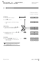
Restoring the transducer to its factory settings.
The detailed procedure for the reset is
described on page 20.
New start value
New end value
BTL7-A/C/E/G5 _ _ -M _ _ _ _ -K(8)-NEX-SR32/K_ _ _
Micropulse Transducer - Rod Style
Summary of Contents for BTL7-A M Series
Page 2: ...www balluff com ...
Page 4: ...www balluff com ...
Page 30: ...www balluff com ...
Page 56: ...www balluff com ...
Page 82: ...www balluff com ...
Page 108: ...www balluff com ...
Page 134: ...www balluff com ...
Page 159: ......


