background image

www.balluff.com

5

english

1.1 

Validity

This guide provides all the information required for safe use 

of the IO-Link Wireless Bridge.
It applies to the following models:
– 

BNI IOW-560-W01-K022 

Order code: BNI00H3

Read this guide and the other applicable documents 

completely before installing and operating the product.

Original User’s Guide

This guide was created in German. Other language 

versions are translations of this guide.
© Copyright 2021, Balluff GmbH

All content is protected by copyright. All rights reserved, 

including the right to reproduce, publish, edit and translate 

this document.

1.2 

Other applicable documents

Additional information about this product can be found at 

www.balluff.com

 on the product page, e.g. in the 

following documents:
–  Data sheet

–  Declaration of Conformity

–  Disposal

1.3 

Symbols and conventions

Individual action

 instructions

 are indicated by a preceding 

triangle.


Instruction 1

Action sequences 

are numbered consecutively:

1. 

Instruction 1

2. 

Instruction 2

Numbers

 unless otherwise indicated are decimals 

(e.g. 23). Hexadecimal numbers are represented with a 

preceding 0x (e.g. 0x12AB).

Note, tip

This symbol indicates general notes.

1.4 

Explanation of the warnings

Always observe the warnings in this guide and the 

measures described to avoid hazards.
The warnings used here contain various signal words and 

are structured as follows:

SIGNAL WORD

Type and source of the hazard

Consequences if not complied with


Measures to avoid hazards

The individual signal words mean:

NOTICE

Identifies a danger that could lead to 

damage to or 

destruction of the product

.

  DANGER

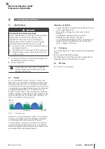
The general warning symbol in conjunction with the 

signal word DANGER identifies a hazard which, if not 

avoided, will

 certainly result in death or serious 

injuries

.

1.5 

Technical terms and abbreviations used

IOLW

IO-Link Wireless

1.6 

Pictures

Product views and pictures in these operating instructions 

may differ from the specified product.

About this guide

BNI IOW-560-W01-K022

Network interface

Summary of Contents for BNI IOW-560-W01-K022

Page 1: ...deutsch Betriebsanleitung english User s guide BNI IOW 560 W01 K022...

Page 2: ...www balluff com...

Page 3: ...BNI IOW 560 W01 K022 Betriebsanleitung deutsch...

Page 4: ...www balluff com...

Page 5: ...8 4 2 Bedien und Anzeigeelemente 9 4 3 Bedruckung 9 5 Einbau und Anschluss 10 5 1 Einbau 10 5 2 Elektrischer Anschluss 10 5 2 1 Spannungsversorgung 10 5 2 2 IO Link 10 6 Inbetriebnahme und Betrieb 11...

Page 6: ...4 deutsch 9 Zubeh r 14 9 1 IO Link Wireless Hub BNI IOW 302 W01 K080 14 9 2 Profinet IO Link Wireless Master BNI PNT 565 W01 K079 14 BNI IOW 560 W01 K022 Netzwerkschnittstelle...

Page 7: ...Handlungsabfolgen werden nummeriert dargestellt 1 Handlungsanweisung 1 2 Handlungsanweisung 2 Zahlen ohne weitere Kennzeichnung sind Dezimalzahlen z B 23 Hexadezimale Zahlen werden mit vorangestell te...

Page 8: ...darf dort nicht eingesetzt werden in sicherheitsgerichteten Anwendungen in denen die Personensicherheit von der Ger tefunktion abh ngt in explosionsgef hrdeten Bereichen im privaten Umfeld Produkt ist...

Page 9: ...Transport Produkt in Originalverpackung bis zum Verwendungs ort transportieren 3 3 Lagerbedingungen Produkt in Originalverpackung lagern Umgebungsbedingungen beachten siehe Umge bungsbedingungen auf S...

Page 10: ...dard f r W Bridge Ger te und ist Teil einer IO Link Wireless Umgebung Sie kommuniziert mit einem IO Link Wireless Master Dazu wird ein IO Link Wireless Master siehe Zubeh r auf Seite 14 ben tigt ein I...

Page 11: ...D Signal Bedeutung Gr n statisch Spannung liegt an Aus keine Spannung Tab 4 1 Power LED Status LED Signal Bedeutung Magenta Keinie Drahtlosverbindung Blau Wireless Bridge ist betriebsbereit Gr n Betri...

Page 12: ...mit einem Kabel mit der IO Link Wireless Bridge verbunden werden ACHTUNG Produktbesch digung Das Produkt verf gt nicht ber einen Verpolungsschutz Wird das Ger t falsch angeschlossen kann es irrepara b...

Page 13: ...en zwischen zwei Frequenz b ndern betrieben werden die f r WLAN vorgesehen sind Hierf r werden die vom WLAN genutzten Frequenzen f r den IO Link Wireless Master gesperrt Bild 6 1 Power WLAN IOLW IOLW...

Page 14: ...O Link Wireless Bridge scannen und ber den Webserver mit dem Master koppeln Abwechselnd Blau und Gelb Die IO Link Wireless Bridge ist erfolgreich mit dem Master gepaart aber das IO Link Ger t ist nich...

Page 15: ...5 M12 A codiert 5 polig Buchse 8 4 Schnittstelle Kommunikationsschnittstelle IO Link IO Link Wire less Version 1 1 Baud Rate COM1 4 8 kBaud COM2 38 4 kBaud COM3 230 4 kBaud 8 5 Material Geh usemateria...

Page 16: ...auf der Produktseite 9 1 IO Link Wireless Hub BNI IOW 302 W01 K080 Bestellcode BNI00FF Bild 9 1 IO Link Wireless Hub 9 2 Profinet IO Link Wireless Master BNI PNT 565 W01 K079 Bestellcode BNI00FE Bild...

Page 17: ...BNI IOW 560 W01 K022 User s Guide english...

Page 18: ...www balluff com...

Page 19: ...g and display elements 9 4 3 Labeling 9 5 Installation and connection 10 5 1 Installation 10 5 2 Electrical connection 10 5 2 1 Power supply 10 5 2 2 IO Link 10 6 Startup and operation 11 6 1 Startup...

Page 20: ...4 english 9 Accessories 14 9 1 IO Link Wireless Hub BNI IOW 302 W01 K080 14 9 2 Profinet IO Link Wireless Master BNI PNT 565 W01 K079 14 BNI IOW 560 W01 K022 Network interface...

Page 21: ...Instruction 1 Action sequences are numbered consecutively 1 Instruction 1 2 Instruction 2 Numbers unless otherwise indicated are decimals e g 23 Hexadecimal numbers are represented with a preceding 0...

Page 22: ...s and areas and may not be used there In safety oriented applications in which personal safety depends on the device function In explosive atmospheres in domestic settings product is class A EMC limit...

Page 23: ...bracket 3 2 Transport Transport product to location of use in original packaging 3 3 Storage conditions Store product in original packaging Observe ambient conditions see Ambient conditions on page 13...

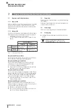
Page 24: ...for W Bridge devices and is part of an IO Link wireless environment It communicates with an IO Link Wireless Master The required components are an IO Link Wireless Master see Accessories on page 14 an...

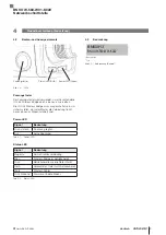
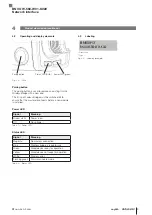
Page 25: ...al Meaning Green static Power is on Off No voltage Tab 4 1 Power LED Status LED Signal Meaning Magenta No wireless connection Blue Wireless bridge is ready for use Green Wired device ready for operati...

Page 26: ...ireless Bridge directly or via an M12 connector with a cable NOTICE Product damage The product does not have reverse polarity protection If the device is connected incorrectly it may be irreparably da...

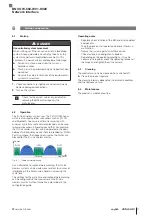
Page 27: ...y bands that are intended for WLAN For this purpose the frequencies used by the WLAN are blocked for the IO Link wireless master Fig 6 1 Power WLAN IOLW IOLW ISM band IOLW Frequency WLAN Radio network...

Page 28: ...ink Wireless Bridge Scan the IO Link Wireless Bridge again and pair it with the master via the web server Alternating blue and yellow The IO Link Wireless Bridge is successfully paired with the master...

Page 29: ...d 5 pin plug IO Link5 M12 A coded 5 pin socket 8 4 Interface Communications interface IO Link IO Link Wireless Version 1 1 Baud rate COM1 4 8 kBaud COM2 38 4 kBaud COM3 230 4 kBaud 8 5 Materials Housi...

Page 30: ...f com on the product page 9 1 IO Link Wireless Hub BNI IOW 302 W01 K080 Order code BNI00FF Fig 9 1 IO Link Wireless Hub 9 2 Profinet IO Link Wireless Master BNI PNT 565 W01 K079 Order code BNI00FE Fig...

Page 31: ......

Page 32: ...ngshan Rd 8F Building A Yunding International Commercial Plaza 200125 Pudong Shanghai Phone 86 400 820 0016 Fax 86 400 920 2622 service cn balluff com cn DACH Service Center Germany Balluff GmbH Schur...

Reviews: