Balluff BIS L-409 Series Quick Manual Download Page 6

6

BIS L-09-... processors together with the other components of the BIS L system comprise the 
identification system. 
They may be used only for this purpose in an industrial environment corresponding to Class A of 
the EMC Law.
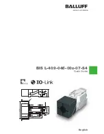
This description applies to the compact processors in the BIS L-09-... series.

Installation and startup

Installation and startup are to be performed only by trained specialists. Any damage resulting 
from unauthorized manipulation or improper use voids the manufacturer's guarantee and war-
ranty.
When connecting the processor to an external controller, observe proper selection and polarity of 
the connection as well as the power supply.
The processor must be powered only using approved power supplies 

(see “Technical data” 

starting on page 16)

.

Attention!

This is a Class A device. This device may cause RF disturbances in residential areas; 

in such a case the operator may be required to take appropriate countermeasures.

Operation and testing

The operator is responsible for observing local prevailing safety regulations.
When defects and non-clearable faults in the Identification System occur, take it out of service 
and secure against unauthorized use. 

Attention!

The pictogram used with the word “Caution” warns of a possible hazardous situation 

affecting the health of persons or equipment damage.  Ignoring these warnings can 

result in injury or equipment damage.

Always observe the described measures for preventing this danger.

2.1  Intended use

2.2  General safety 

notes

2.3  Meaning of the 

warnings

Safety

2

BIS L-409 IO-Link Device

Processor

Summary of Contents for BIS L-409 Series

Page 1: ...Quick Guide English BIS L 409 045 00x 07 S4 A 41...

Page 2: ...www balluff com...

Page 3: ...g of the warnings 7 Getting Started 8 3 1 Mechanical connection 8 3 2 Electrical connection 11 Basic knowledge 13 4 1 Function principle of Identification Systems 13 4 2 System topology 14 4 3 Read di...

Page 4: ...ints Entry 1 Entry 2 Action instructions are indicated by a preceding triangle The result of an action is indicated by an arrow Action instruction 1 Action result Action instruction 2 Numbers Decimal...

Page 5: ...age EMC Electromagnetic Compatibility LSB Least Significant Bit MSB Most Significant Bit PC Personal Computer SIO Standard IO SPDU Service Protocol Data Unit PLC Programmable Logic Controller TCP Tran...

Page 6: ...owered only using approved power supplies see Technical data starting on page 16 Attention This is a Class A device This device may cause RF disturbances in residential areas in such a case the operat...

Page 7: ...crews Note maximum tightening torque of 15 Ncm In addition to the processor with integrated read head the following processors with remote read head are available The processors with remote read head...

Page 8: ...41 Fig 3 Processor BIS L 409 045 003 07 S4 dimensions in mm A Clear zone A A 41 Fig 4 Processor BIS L 409 045 004 07 S4 dimensions in mm A Clear zone Getting Started 3 BIS L 409 IO Link Device Process...

Page 9: ...stance Y BIS L 409 001 1 m 1 m BIS L 409 002 0 5 m 0 3 m BIS L 409 003 0 5 m 0 3 m BIS L 409 004 0 5 m 0 3 m Note When installing two BIS L 409 on metal there is normally no mutual interference Unfavo...

Page 10: ...dicators on the processor Item LED Display Function 3 LED 1 green Supply voltage present 4 LED 2 yellow Tag Present IO Link port M12 A coded female PIN Function 1 24 V 2 NC 3 GND 4 C Q Connect data li...

Page 11: ...is set using jumpers in the processor X4 IO Link mode jumper setting as shown in Fig 7 factory default setting Service mode to be used only by Balluff service The baud rate is set using two DIP switc...

Page 12: ...a carrier signal which is picked up by the data carrier from within a certain distance As soon as the data carrier is powered up by the carrier signal a static read operation takes place The processo...

Page 13: ...www balluff com 13 Fig 9 BIS L 409 topology 1 PLC 2 PC 3 ProfiBus 4 IO Link Master 5 Processors BIS L 409 4 2 System topology Basic knowledge 4 BIS L 409 IO Link Device Processor...

Page 14: ...tion data carrier is powered by the read head using a carrier signal In order to ensure data integrity data transmission between the data carrier and processor can be monitored using a check procedure...

Page 15: ...ta when used with data carriers installed in clear zone When v 0 static Distance mm read Offset from center axis at distance mm 0 20 0 35 0 45 0 15 BIS L 200 03 BIS L 100 05 25 15 BIS L 201 03 BIS L 1...

Page 16: ...301 489 1 3 EN 61000 4 2 3 4 5 6 EN 300 330 1 Class A Level 3A 3A 4A 2A 3A Power class 5 Vibration shock EN 60068 Part 2 6 27 29 64 32 Two LEDs on the communications module indicate the status LED in...

Page 17: ...ad Offset from center axis at distance mm 0 10 0 15 0 20 BIS L 200 03 BIS L 100 05 15 10 BIS L 201 03 BIS L 101 05 18 12 12 BIS L 203 03 BIS L 103 05 10 4 Housing material Plastic PBT Read head housin...

Page 18: ...301 489 1 3 EN 61000 4 2 3 4 5 6 EN 300 330 1 Class A Level 3A 3A 4A 2A 3A Power class 5 Vibration shock EN 60068 Part 2 6 27 29 32 64 Two LEDs on the communications module indicate the status LED in...

Page 19: ...zone When v 0 static Distance mm read Offset from center axis at distance mm 0 5 0 8 0 11 BIS L 203 03 BIS L 103 05 7 4 Housing material Plastic PBT Read head housing material CuZn nickel plated Wirin...

Page 20: ...301 489 1 3 EN 61000 4 2 3 4 5 6 EN 300 330 1 Class A Level 3A 3A 4A 2A 3A Power class 5 Vibration shock EN 60068 Part 2 6 27 29 32 64 Two LEDs on the communications module indicate the status LED in...

Page 21: ...ith data carriers installed in clear zone When v 0 static Distance mm read Offset from center axis at distance mm 0 10 0 15 0 20 BIS L 200 03 BIS L 100 05 15 10 BIS L 201 03 BIS L 101 05 18 12 12 BIS...

Page 22: ...terface IO Link Ambient temperature range 0 C 70 C EMV EN 301 489 1 3 EN 61000 4 2 3 4 5 6 EN 300 330 1 Class A Level 3A 3A 4A 2A 3A Power class 5 Vibration shock EN 60068 Part 2 6 27 29 32 64 Two LED...

Page 23: ...409 Plastic housing IO Link Software type 045 Software number IO Link Version 001 Coil 34 mm 002 Offset read head M18 0 5 m cable 003 Offset read head M12 0 5 m cable 004 Remote read head C 305 housi...

Page 24: ...luff GmbH Schurwaldstrasse 9 73765 Neuhausen a d F Germany Phone 49 7158 173 0 Fax 49 7158 5010 balluff balluff de No 858280 00 000000 Edition 0805 Subject to modification www balluff com www balluff...

Reviews: