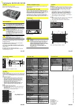


This guide is valid for the following devices:
BAE PS-XA-1W-12-085-54 (ordering code BAE00MC)
The user's guide can also be found on the Internet at
www.balluff.com
.
This device is a primary switched-mode power supply for integration
in control panel installations or integral applications where access to
the power supply is restricted (contact protection).
The device is suitable for pollution severity level 2
.
Modifications to the device or non-approved use are not permitted
and will result in loss of warranty and void any liability claims against
the manufacturer.
Switched-mode power supplies. BAE PS-XA-1W-12-085-054
Safety notes
Validity
Downloading the user's guide
Proper use
Dimensions
Installation
Installation
Before commissioning, read the user's guide carefully!
These devices must not be used in applications in which
the safety of persons is dependent on the function of the
device (not a safety component acc. to EU Machinery
Directive).
Important!
Connect the device to power supply in accordance with
local regulations and standards. Do not cover the device!
Provide enough space around the device for cooling.
Otherwise, the device may switch off due to overheating.
Operating the device in an overheated state for a
prolonged period shortens the service life of the device.
The housing may become hot during operation!
Always switch the power off before connecting /
disconnecting plug connections!
DANGER
due to high voltages!
Contact with unprotected conductors and components
can result in fatal electric shock or severe burns.
Before starting work on the device, disconnect the power
supply and secure it to prevent it from being restarted.
Do not insert foreign objects into the device. Keep away
from fire and water.
DANGER
due to electric arcing and deadly electric
shocks!
Do not modify the installation while the device is
operating! This also applies to the secondary side.
Installation and startup are to be performed by trained technical
personnel only.
The
operator
is responsible for ensuring that local safety regulations
are observed.
In particular, the operator must take measures to ensure that a defect
in the device will not result in hazards to persons or equipment.
If defects and persistent faults occur in the switched-mode power
supply, take it out of service and secure it to prevent any unautho-
rized use.
158
97
Ø3.5
Ø3.5
38
Fig. 1: Dimensions
Fig. 2: Fastening the switched-mode power supply. Position A
Installation
FWe recommend leaving a gap of 25 mm around the device to allow
for adequate ventilation and cooling. Do not obstruct the ventilation
holes.If multiple switched-mode power supplies are installed next to
each other, provide enough distance between the devices to ensure
adequate ventilation.
1. Secure the device with M3 screws in accordance with Figure 2
and 3. Please note: the screws may not exceed the maximum
length (4 mm for Position A, 5 mm for Position B). Longer screws
can cause a short-circuit.
2. Lay the input and output power cables separately from each other
to prevent interference.
Removal
1. Switch off the power supply and disconnect the system from the
power grid. Disconnect all connectors from the power supply.
2. Loosen the screws and carefully remove the device.
Installation position A
Installation (continued)
Connections
Technical data
Technical data
Installation position B
Fig. 3: Fastening the switched-mode power supply. Position B
Internal fuse
The internal input fuse protects the device and must not be replaced
by the user. If an internal fault occurs, return the device to the
manufacturer as a precautionary measure.
Electrical connections.
Electrical connections
−
For data on permissible loads, see the "Technical data" table.
−
Only use commercial cables suitable for the specified current and
voltage values.
−
For flexible cables, make sure that all strands are secured in the
terminal (possible risk of a short-circuit).
−
Make sure the polarity at the output is correct.
−
If necessary, a manually controlled separating element for
isolating the power supply must be used.
−
Device and power cables must be properly protected by a fuse.
Grounding
Do not operate without a GND connection!
−
The unsecured ground conductor must be connected to GND
(insulation class 1).
−
The secondary side is not grounded. If necessary, the plus or
minus terminal can be grounded
+
+
–
–
PE
N
L
V ADJ
OUT
Max. tightening torque for
plug connector: 1,2 Nm
Fig. 4: Connections
Balluff GmbH
Schurwaldstraße 9
73765 Neuhausen a.d.F.
Germany
Tel. +49 7158 173-0
Fax +49 7158 5010
[email protected]
Dok.-Nr
./Doc. no.
DE/EN . I14; Änderungen vorbehalten/Subject to modification
916 459
Ambient conditions
Operating temperature
–40...+71 °C
Storage temperature
–40...+85 °C
Relative humidity
20%...95% RH
Cooling
Free air convection
Approvals and standards
UL / cUL
UL 60950-1 Recognized
TÜV
EN 60950-1
CE
EN 61000-6-3, EN 61000-3-2,
EN 61000-3-3,EN 61000-6-2,
EN 61000-4-2, EN 61000-4-3,
EN 61000-4-4, EN 61000-4-5,
EN 61000-4-6, EN 61000-4-8,
EN 61000-4-11, EN 61204-3,
EN 55022 Class B
Electrical data
Isolation voltage
3000 V AC/ 4242 V DC
Isolation resistance
>100 M
Ω
Turn-on time
< 1500 ms
Turn-on time with capacitive load
< 2000 ms 7000 µF
Rise time
< 150 ms
Rise time with capacitive load
< 500 ms 7000 µF
Switching frequency f
100 kHz (typ)
Parallel mode
In line
Not possible
Max. 2 devices
Temperature coefficient
±0.03% / °C
Efficiency (Typ) / (Avg)
87% / 87%
Input data
Input voltage
100...240 V AC
Input voltage range
88 V AC...264 V AC
120 V DC...375 V DC
Rated input current
max. 1500 mA
Inrush current
115 V AC
230 V AC
< 35 A
< 60 A
Frequency
47...63 Hz
Input fuse
T3.15 A / 250 V AC, intern
Power Factor Correction (PFC)
meet EN61000-3-2 Class D
Output data
Nominal output voltage
12 V DC
Initial voltage setting
12 V + 1%
Nominal output current
8.5 A
Output wattage
102 W
Voltage trim range @0.8 lo
10.8...13.2 V DC
Derating
3% / °C from 56 °C to +71 °C
Ripple @ lo nom
100 mV p-p
Line regulation
±0.5%
Load regulation
±1.0%
Rated overload protection
130%...160%
Over voltage protection @0.8 lo
13.8...16.2 V DC
Output short-circuit
Hiccup mode
Hold-up time (230 V AC)
> 70 ms
Dropout time
< 150 ms
Mechanical data
Housing material
Metal
Max. required free space
25 mm on all sides of the
device
Weight
530 g
Dimensions (L x W x H) mm
158 x 97 x 38
Connection
AWG 22...14
2
0,2...2 mm
Fastening
M3 screws, max. length
4 or 5 mm
5.50
117
23
3 x M3
L = max. 5 mm
150
19.30
28.80
28.50
10.80
18
Ø3.5
Ø3.5
23
5
153
2 x M3
L = max. 4 mm
78
158
9.50
65
97
84.50
7


