Cut here for
80
≤
T
≤
100
mm(Optional)
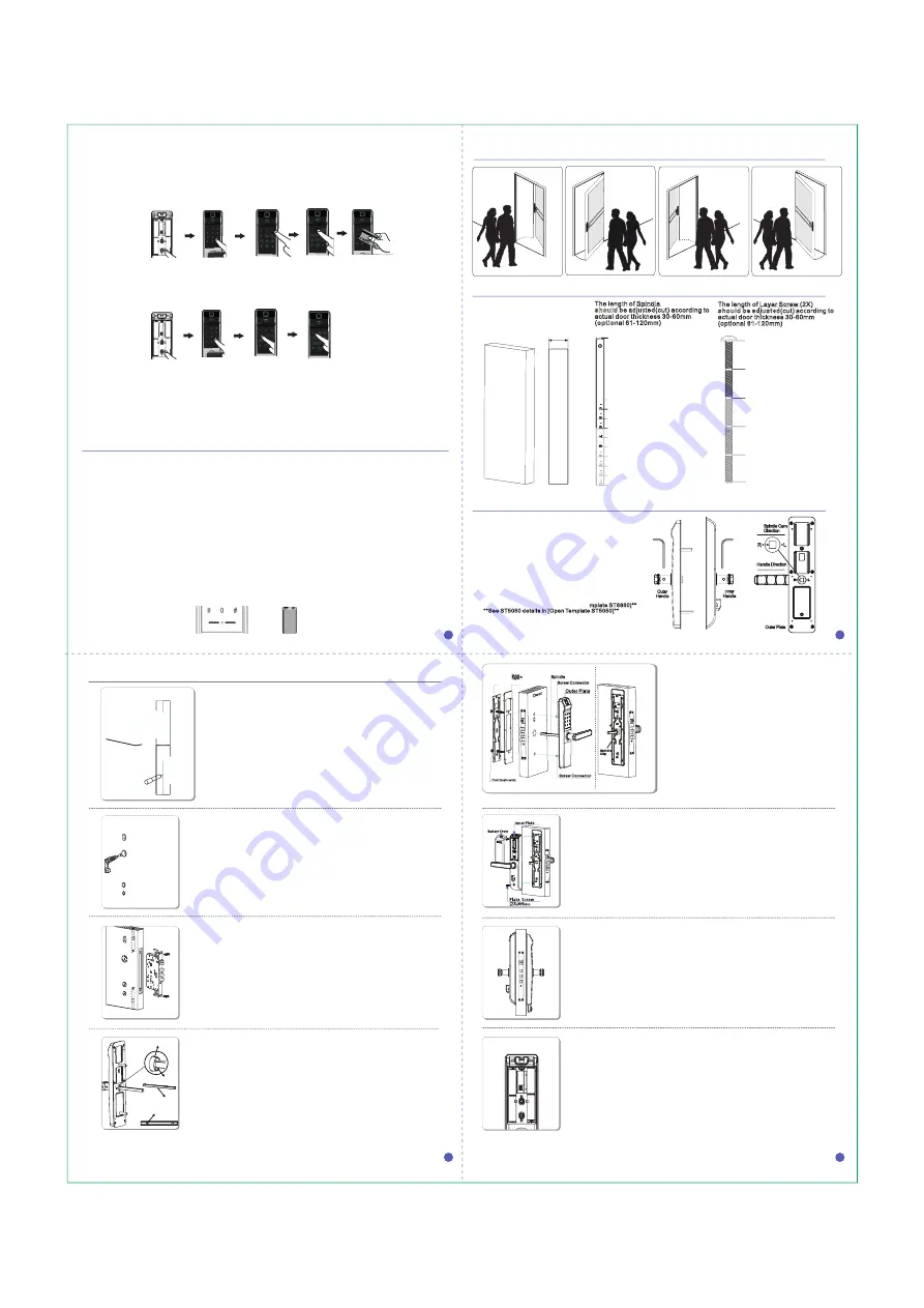
Direction Change on the Lock Body:
**See ST6860 details in [Open Te
mplate ST6860]**
**See ST5050 details in [Open Template ST5050]**
Door Thickness
supports: 30
-60mm
(optional 61-120mm)
4
5
6
7
8
9
10
11
12
Door Thickness Checks and Preparations Before Installation
The length of Spindle
should
b
e adju
s
te
d
(cut) according to
actual door thickness 30-60mm
(
optio
nal 61-120mm)
Thickness
Base line
The length of Layer Screw (2X)
should be a
dj
us
te
d(cut)
ac
c
ording to
actual door thickness 30-60mm
(optional
61-12
0mm)
Base line
Cut here for
T
=
40
mm
Cut here for
T
=
50
mm
Cut here for
T
=
60
mm
Cut here for
T
=
70
mm
Cut here for
T
=
80
mm
Cut here for
T
=
90
mm(Optional)
Cut here for
T
=
100
mm(Optional)
Cut here for
T
=
110
mm(Optional)
Cut here for
T
=
120
mm(Optional)
Cut here for
T
≤
40
mm
Cut here for
40
≤
T
≤
60
mm
Cut here for
60
≤
T
≤
80
mm
Cut here for
T
≤
120
mm(Optional)
Door
Door Open Direction Checks and Preparations Before Installation
Direction Changes on Lock Body and Handles
Direction Change on the Handle:
1.Loosen the allen screws � on both
outer&inner handle
s with allen driver �
2.Turn the handles to the reversed direction
3.Fasten the allen screws � to fix both
outer&inner handles
4.Turn Spindle Cam � on Outer Plate
and make sure its arrow direction is
pointing to the same direction as handle.
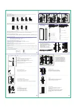
1.Draw Line
Firstly draw Handle Central Line and Side Central Line
according to proper height for lock installation;
Secondly put the Open Template on the door,
and make sure all Handle Central Lines, Side Central Lines,
and Edge lines are fully matched;
Finally mark the lines according to the Open Template for
opening holes and grooves.
2.Open Holes and Grooves
Use correct tools to open holes and
grooves according to drawn lines.
Installation
Instruction
Important Note: keep the door open before installation being finished
Door
Handle
Central Line
3.Install Lock Body (ST6860)
Put the Lock Body into the right hole as left,
then fasten it firmly with Wood Screws(3X).
**See Lock Body ST5050(optional) details in Open Template [ST5050]**
4.Install Spindle
Adjust (cut) the right length of Spindle
according to actual door thickness,
insert it into Spindle Hole and make
sure Locating Pin on Spindle fully fit
into Locating Hole until Spindle is fixed.
5.Install Outer Plate
Put Outer Plate on the door and
make sure its cable, screw connectors
and Spindle goes through right holes;
Then attach both Inner Rubber Layer
and Inner Metal Layer on the other side
with Layer Fixing Screws(2X) and put
on Spindle Cap on the other side of
Spindle. Finally press down the handle
to check if it works well; otherwise,
adjust it before fastening all the screws.
6.Install Inner Plate
Remove Spindle Cap , and joint the cable
from Outer Plate to the socket on Inner Plate.
Then fasten Inner Plate with Plate Screws(2X).
7.Check
Press down both Outer/Inner Handles, turn the Key,
turn the Knob to check if the lock works all well;
otherwise, please adjust or reinstall it.
8
.
Install Batteries
Put on 4pcs AA batteries(optional), and make sure
their po) and negative(-) poles stay in
correct positions.
Then use any fingerprint (NF-21A only), any password
and/or any card to test lock openings and operations.
If any failure, please re-check and re-adjust above
installations.
5
7
8
6
Handle Direction
Spindle Cam
Direction
②
③
③
Cut here for
T
=
30
mm
Right
To
Outside
Right
To
Inside
Left
To
Inside
Outer
Handle
Inner
Handle
Outer Plate
Left
To
Outside
②
Spindle
Locating Hole
Locating Pin
Spindle Hole
Handle
Central Lin
e
S
id
e C
e
n
tr
a
l L
in
e
E
d
g
e L
in
e
E
d
g
e L
in
e
E
d
g
e L
in
e
E
d
g
e L
in
e
Inner
Metal
Layer
Inner
Rubbe
r
Laye
r
Door
Spindle
Outer Plate
Plate FixingScrew
(2X)
Screw Connector
Screw Connector
Spindle
Cap
①
②
③
④
Operaciones destacadas
16.Contraseña segura
Para aumentar los niveles de seguridad de las contraseñas, el sistema no admite contraseñas tales como:
1.
Números consecutivos: 123456, 1234567, 12345678,...etc.
2.
Dígitos repetidos: 000000, 111111, 222222, ...etc.
17.Protección de contraseña contra espionaje
El usuario podrá digitar otros números antes y/o después de su contraseña
.
Por ejemplo, si la contraseña es 112233, el sistema aceptará, con un máximo de 30 dígitos:
121122333, 123112233123, 123123112233321321, etc
.
19.Alarma por batería baja
Si el voltaje de las baterías es inferior a 4.8V, sonará la alarma en cada apertura de la cerradura para recordarle que cambie
las pilas.
21.Fuente de alimentación de emergencia
Si se agotan las baterías, apoye una batería de 9V en las barras del panel exterior e ingrese con la huella, contraseña o tarjeta.
Recuerde ingresar y cambiar las pilas
Barras conectoras
Batería de 9V
18.Alarma contra intrusos
El sistema se bloqueará durante 180 segundos si se ingresan erróneamente huellas, contraseñas o tarjetas 5 veces
consecutivas.
Presione [I] o [C] para desactivar la alarma.
12.Eliminar tarjetas
Retire la tapa de las baterías y presione el botón [C]. Coloque la huella o contraseña administradora
y presione el [3] para
acceder al siguiente sub-menú:
[1]
:Eliminar una única tarjeta apoyándola en el sensor o con el número de ID.
[
2]:
Eliminar todas las tarjetas
Seleccione una de las opciones y confírmela con [#], o presione [*] para cancelar.
13.Eliminar control remoto
Retire la tapa de las baterías y presione el botón [C]. Coloque la huella o contraseña administradora
y presione el [4] y el [1] para
para eliminr todos los controles. Digite [#] para confirmar o [*] para cancelar.
Presione
[
4
]
en el sub-menú
para eliminar todos
14.Restaurar a estado de fábrica (opción 1)
Retire la tapa de las baterías y presione el botón [C] durante 6 segundos
. Luego
coloque la huella o contraseña administradora.
Se eliminarán absolutamente todas las huellas, contraseñas, tarjetas y controles remotos registrados.
Battery Cover
Plate Screw
(2X
)
M4
X18.5
Inner Plate
①
①
20.
Si la cerradura está bloqueada con la perilla interna, sólamente podrán ingresar las huellas o contraseñas administradoras
o la llave de emergencia
.
Apoye la tarjeta
o el número
de ID
Seleccione una
opción del
sub-menú
Presione
[C]
Ingrese huella o
contraseña admin.
Presione
[
3
]
en el menú
Presione
[C]
Ingrese huella o
contraseña admin.
Presione
[
3
]
en el menú
14.Restaurar a estado de fábrica (opción 2)
Retire la tapa de las baterías. Saque una de las 4 pilas. Mantenga presionado los botones [I] y [C] y, sin soltarlos, vuelva a
colocar la pila restante.
Se eliminarán absolutamente todas las huellas, contraseñas, tarjetas y controles remotos registrados.


