1
Program
Button
Mounting
Holes
Turnpiece
Lock Button
Cylinder
Settings
Switch
Panel
LED
Keypad
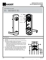
Getting Started
Quick Reference
● Refer to “Quick Reference” area and illustrations to identify components.
● Prepare door, per additional instructions (included) before installing unit.
● IMPORTANT:
Read instructions completely before beginning installation.
Use the checklist below to assure completion of important steps.
□ ATTACH CONNECTOR ..........................................
□ RUN “BOLT DIRECTION” DETERMINATION .......
□ PROGRAM CODE(S) .............................................
□ VERIFY OPERATION .............................................
Section 5
Section 8
Section 9 a, b, c
Section 9 d
Interior
Assembly
Exterior
Assembly
Copyright © 2010 Baldwin Hardware Corporation
Baldwin Keyless Entry Deadbolt Manual PK.9008 / 02/10
Installation & Programming Manual
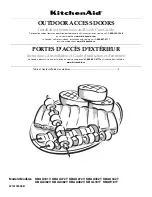
Cylinder
Interior
Assembly
Interior
Cover
Exterior
Assembly
Adapter
Latch
Mounting
Plate
Mounting
Screws
Summary of Contents for 8252 Series
Page 5: ......