- 3 -
Issue 3
Connection Details and Schematic
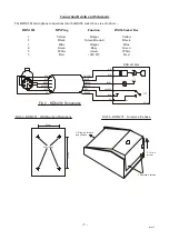
The BDM 201 microphone connections into the BMS6 socket box are as follows ...
BDM 201
DIN Plug
Function
BMS6 Socket Box
1
Yellow
Output
Yellow
2
Black
Screen/Ground
Black
3
Blue
Output
Blue
4
Green
Busy
Green
5
White
Access
White
6
Red
+24V DC
Red
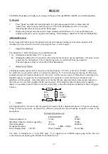
Fig 2 - BDM201 Schematic
0V
+24V
+24V
+24V
0V
BUSY
MIC
MIC
BUSY
ACCESS
+24V
0V
MIC
MIC
BUSY
ACCESS
+24V
0V
PTT
BLACK
RED
WHITE
GREEN
BLUE
YELLOW
PC1146
BDM 201 Mk2
1
2
3
4
5
6
1. Remove 2 screws
2. Lift top
at rear
3. Slide top forward
and off base
9
8
m
m
65mm
4mm fixings
FIG 3a - BDM 201 - Wall Mounting Dimensions
FIG 3b - BDM 201 - To remove the base


